Introduction

Abstract
Industry 4.0 has arrived and some of its key points are IoT, real time data processing, cloud computing, etc. Manual ways of maintaining and checking ambiguity in an industrial environment is very hard and time consuming and contacting the expert for fixing the problem at the same time is quite complex. Instead of manual checking, autonomous surveillance robots will save time and by checking the environment near the machine, it can generate a report and upload it to the cloud. One can easily analyze the working of a plant/machine by checking the data. If the robot finds any emergency condition, then it can turn on the alarm and urgently call for help. By implementing this system, we can reduce the industrial accidents which are very common and most dangerous nowadays. We can save time and labor for other important work and at the same time we can increase the frequency of checking the possible threats like gas leakage, fire, temperature overload.
Motivation
Industry 4.0 is an ongoing phenomena and it’s stated as “An Automation Revolution”. Applying automation in the field of maintenance and surveillance will save time as well as the labor work. Which we can utilize for other important applications. Nowadays everything is decentralizing and possible virtually so one can take the survey by checking the data generated through the robot and utilize a large amount of time and resources. There are on average 3000 occupational accidents happening in industries which are very dangerous. By implementing the necessary automation we can reduce these cases of dangerous accidents.
Description
ISR!
Hardware Specifications
| Component | Description | Datasheet |
|---|---|---|
| De0-Nano | def | De0-Nano |
| N20 Motors | def | - |
| L9110s Motor Driver | def | L9110s |
| 2S li-ion battery | def | - |
| Line Follower Sensor | def | - |
| Xbee s2c Module | def | xbee s2c |
| TCS3200(Color Sensor) | def | TCS3200 |
DE0-Nano Development Board
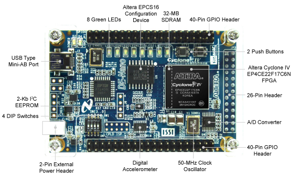
Specification
Cyclone® IV EP4CE22F17C6N FPGA
- 22,320 Logic elements (LEs)
- 594 Embedded memory (Kbits)
- 66 Embedded 18 x 18 multipliers
- 4 General-purpose PLLs
- 153 Maximum FPGA I/O pins
Configuration Status and Set-Up Elements
- On-board USB-Blaster circuit for programming
- FPGA Serial Configuration Device (EPCS)
Clock System
- On-board 50MHz clock oscillator
Expansion Header
- Two 40-pin Headers (GPIOs) provides 72 3.3V I/O pins
- Two 5V power pins, two 3.3V power pins and four ground pins
- One 26-pin header provides 16 3.3V digital I/O pins and 8 analog input pins to connect to analog sensors, etc
Memory Devices
- 32MB SDRAM
- 2Kb I2C EEPROM
General User Input/Output
- 8 green LEDs
- 2 debounced push-buttons
- 4 dip switches
G-Sensor
- ADI ADXL345, 3-axis accelerometer with high resolution (13-bit)
A/D Converter
- NS ADC128S022, 8-Channel, 12-bit A/D Converter
- 50 ksps to 200 ksps
Power Supply
- USB Type mini-AB port (5V)
- Two DC 5V pins of the GPIO headers (5V)
- 2-pin external power header (3.6-5.7V)
Software Specifications
- Quartus Prime Lite 19.1 for programming the FPGA board (Verilog HDL).
- Modelsim
- Github for maintenance of code and project repo online.
- Firebase for hosting resources online (Cloud communication on a server)
- Sqlite for database management.
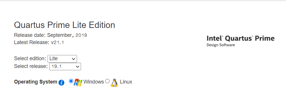
Installation of Quartus Prime 19.1 Lite & ModelSim
Please follow below link for the installation of the softwares.
Please select the options which are displayed below
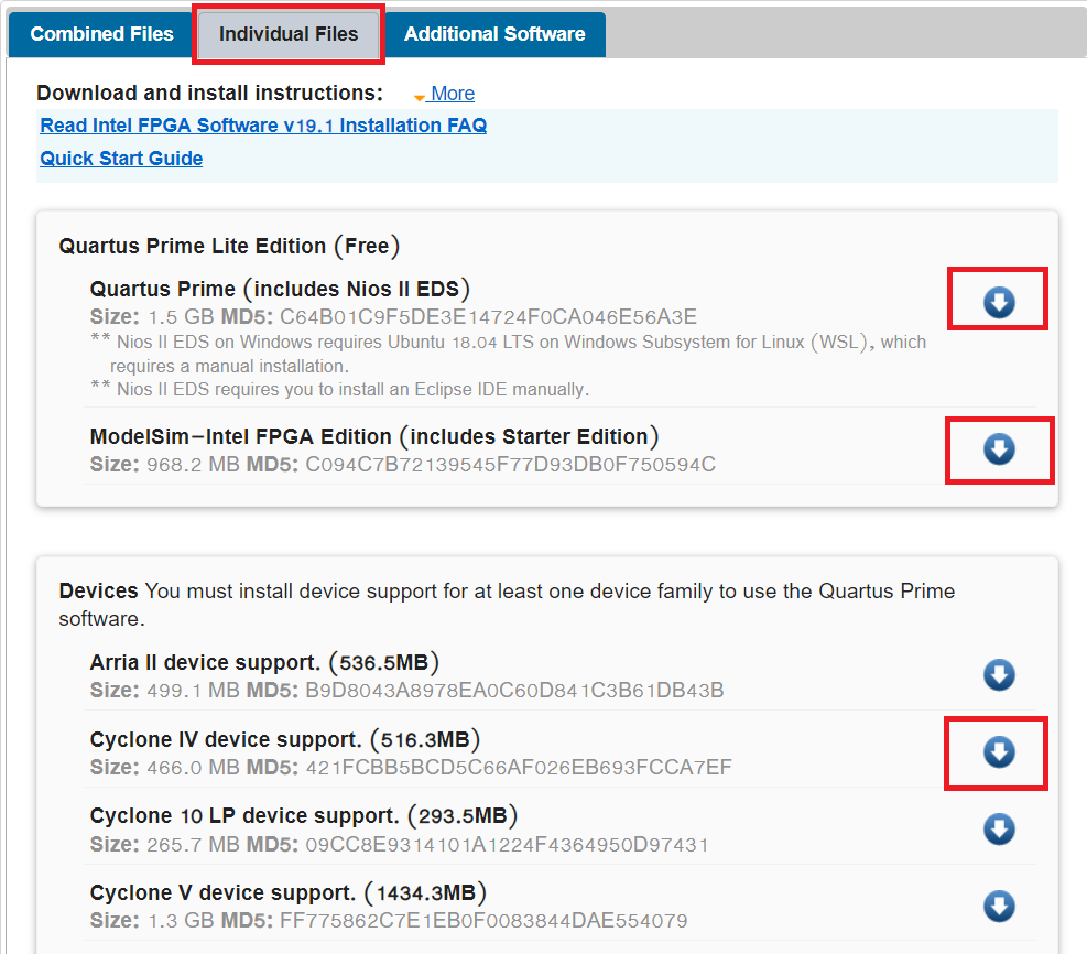
There are two ways for installing the software:
- Installing by downloading
Combined Files - Installing by downloading
Individual Files
We will Download from Individual files since we are working with a perticular board so it will save some data :)
Please select the options which are displayed below and download 3 files for getting started with installation.
After downloading the files this 3 files will be there in download folder or it will be on the perticular path which you have selected.
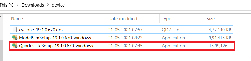
Installation steps
-
Double click on highlited application and install it with the default options.
- At the end it will take some time for getting Quartus and ModelSim installed.
-
After the installation we need to add the device which is
Cyclone 4, It's for getting the support ofde0 - neno board.- copy the
cyclone-19.1.0.670.qdzfile( which is forCyclone IVsupport file) in theC:/intelFPGA lite/19.1/modelsim ase/win32aloemfor getting the support of that device family while working with the project. - QDZ file is a Altera Quartus II Device Package. Altera Quartus is a programmable logic device design software from Altera which is now owned by INTEL.
- copy the
- There is another way of adding the device!
- click on start menu and search for
Device installer
- click on start menu and search for
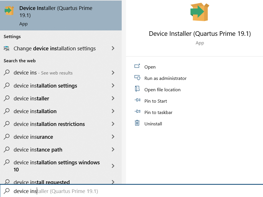
- Open this application and do as directed
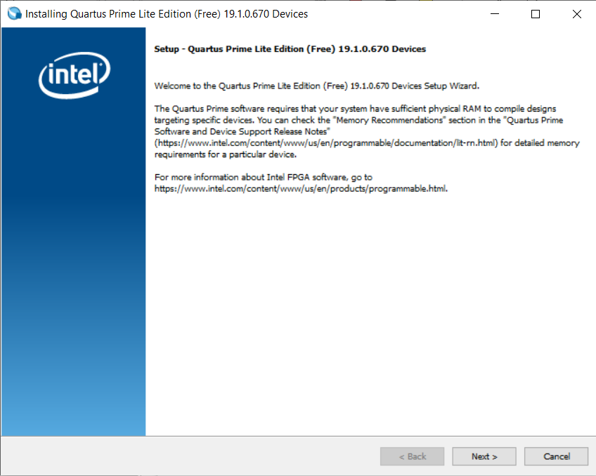
- Click on the next
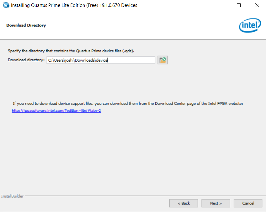
- Select the folder in which you are having
.qdzfile/files and then click on the next.
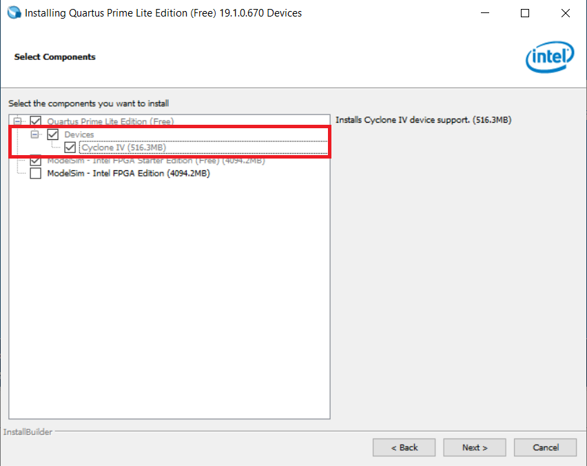
- Select the required device and click on the next and get it done!
Now the installation is done ;)
Getting Started With Quartus
Here we will start with the Quartus software. We will create projects( Which will contains nedessary files), HDL files( It will contain desired hardware implimentation design), waveform vector files( It will contain waveform responce of the HDL description) and test benches( For validating the HDL description).
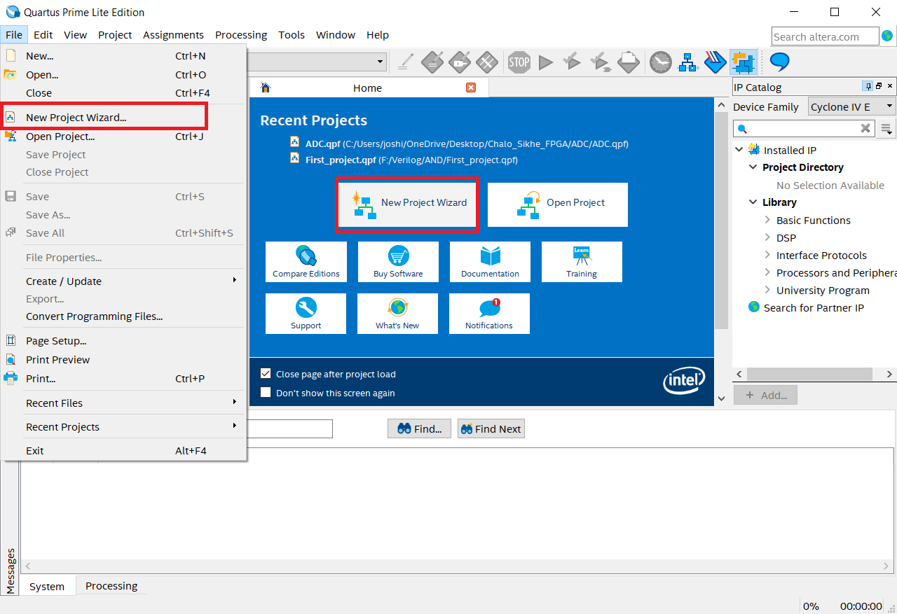
1. Creating a new project
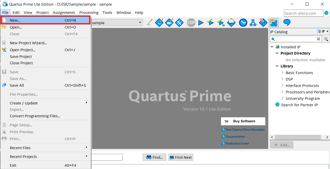
- In order to create the project select any of the option which is highlited below
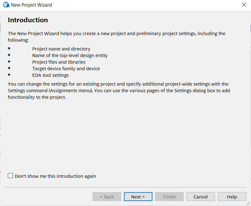
- Now click on the
nextfor further process
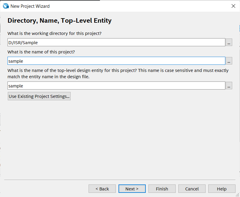
- In below step please select the target folder and give the name of the project and click on the next
Note: If possible then please not select target folder in
C partition
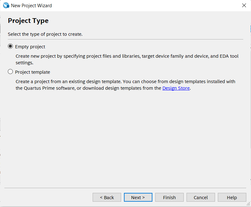
- Click on
empty projectfor manually selecting or adding additional files, libraries, devices, EDA( Electronic Design Automation) tool selection and HDL selection.
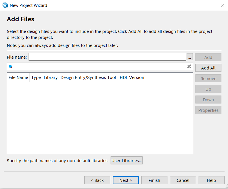
- In add file section directly click on the next, since for now we don't require any files.
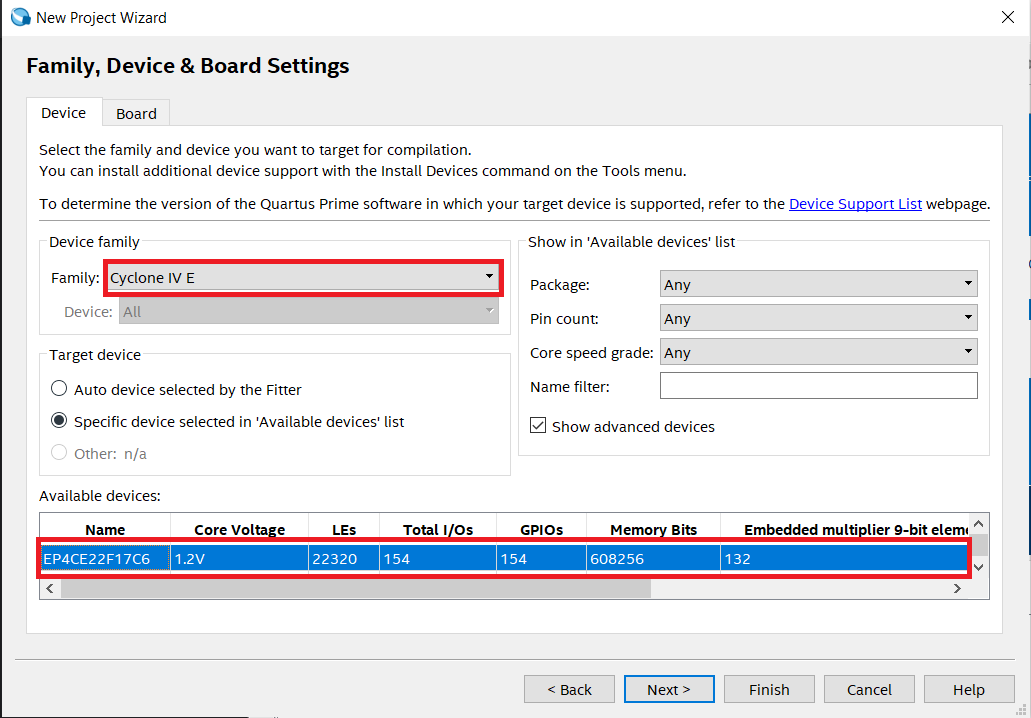
- In this step carefully select the familt which is
Cyclone IV Eand from avalable device selectEP4CE22F17C6. Here insted of scorlling we can search the device by simply giving name in right side.
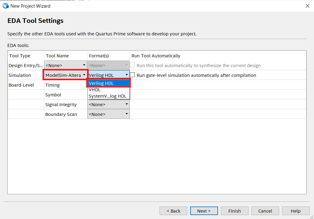
- Select simulation tool as
ModelSimand select simulation format asVerilog HDL.
- There is summery of the selected options and configuration. Once these things are saved then they will not be changed through out the project.
- Click on the
Finishfor successfully creating a new project.
2. Creating a new file in a project
- After creating a project and setting up the Quartus for a perticular boards and configuration by the project creation, We can now add the HDL description in the project by creating a new files( Here
verilog files). - We will firstly start with the creating the
AND gate. As we know it will have 2 input and 1 output.- Here
AandBwill be as input pins andCwill be as output pin.
- Here
Follow the steps for creating a new file:
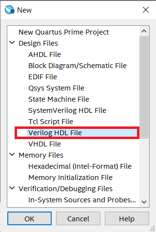
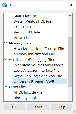
- Click on File --> New
- Select
Verilog HDL Fileand then click onOK.
Here we can also select VHDL as HDL source but for now we are going ahead with Verilog HDl but remember VHDL is also a powerful HDL.
-
For testing please paste the below code in newly created file.
-
Verilog code for AND gate
module AND_GATE        // Module name: AND_GATE
(
	input A,B,        // defining inputs A and B of AND gate
	output C          // defining output of AND gate
);

assign C = A & B;   // Logic implementation
endmodule
- After writing this code press
ctrl + sfor saving the file and give the name same as you given the name of module which isAND_GATEhere. - It's applied for the top level entity so we need to follow this method of naming for top level file which will contain main design which can be individual file or combination of different HDL design files.
3. Compiling or synthesizing the project files
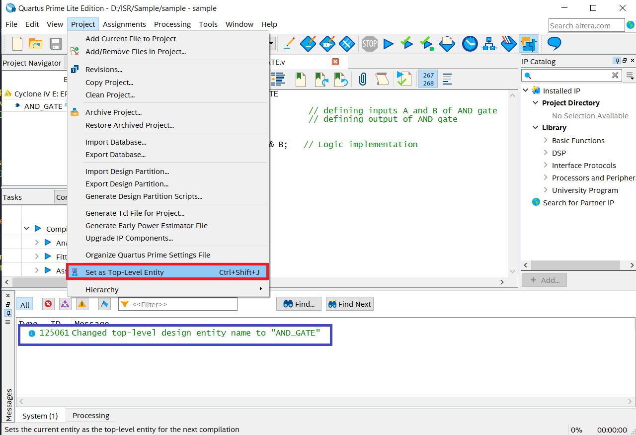
- For compiling the file or design firstly selet it as top level entity.
- After selecting it as top level entity there wil be message highlited as below.
- Click on Start compilation icon or press
ctrl + Lfor compilation ofAND_GATE
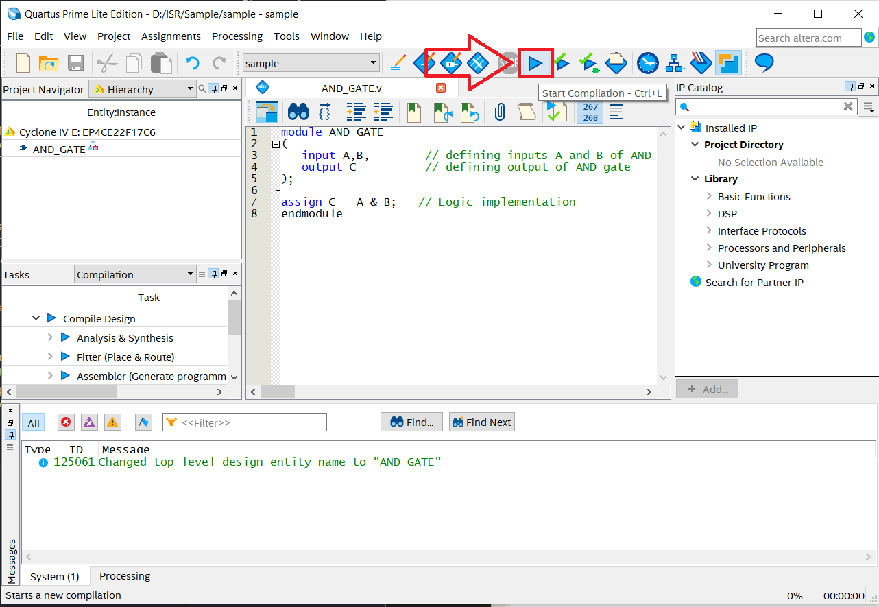
- During the compilation these processes are carried out.
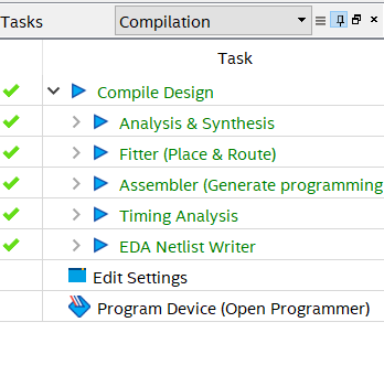
- After compilation if there will not be any error then we can see this kind of message at the end.
- If there is any error then we need to correct the code.

4. Verifying HDL Description
We can perform timing simulation of a perticular module using EDA simulation tools. There are two methods for verifying the designs.
- By appplying manual inputs to the input pins.
- By designing testbench for the module, we can verify the design.
First method
- click on
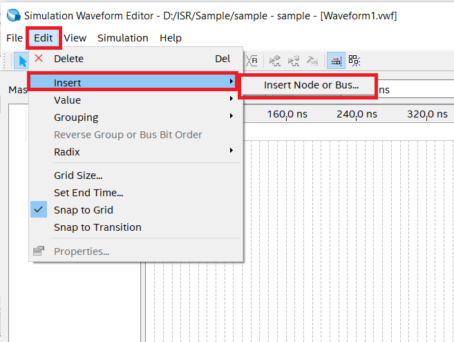
File --> New --> University Program VWF.
- Click on the
Edit --> Insert --> Insert Node or Bus.
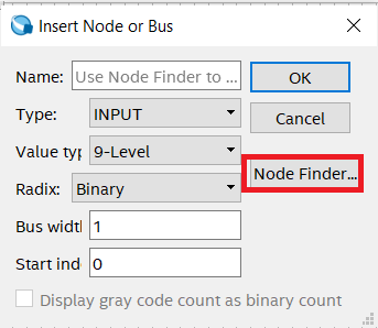
- Click on the
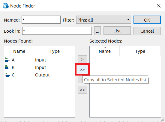
Node Finderfor finding the avalable nodes.
-
Now click on the
Listfor listing own the avalable Nodes.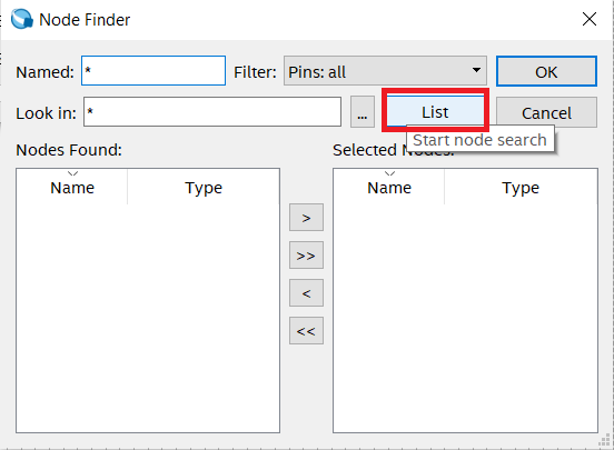
-
Click on the
>>for selecting the avalable nodes. Here we can also select a perticular node by clicking>. and from othere option we can put the selected nodes in to avalable node section. -
After this process click on
OK.
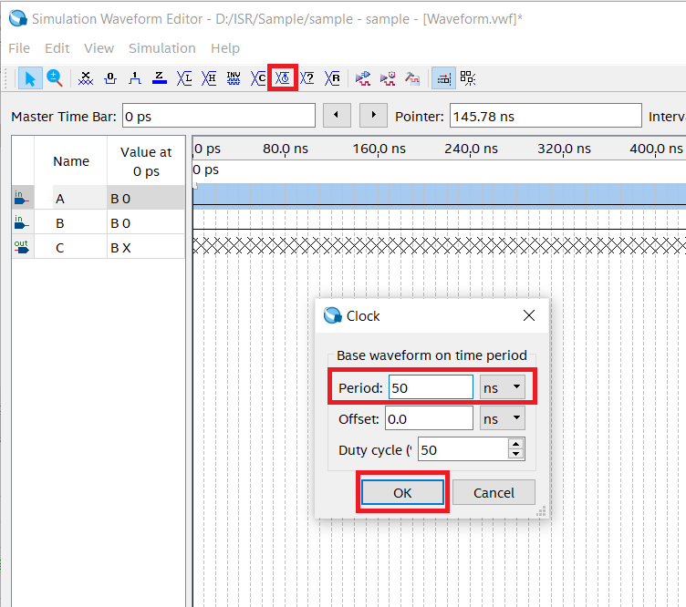
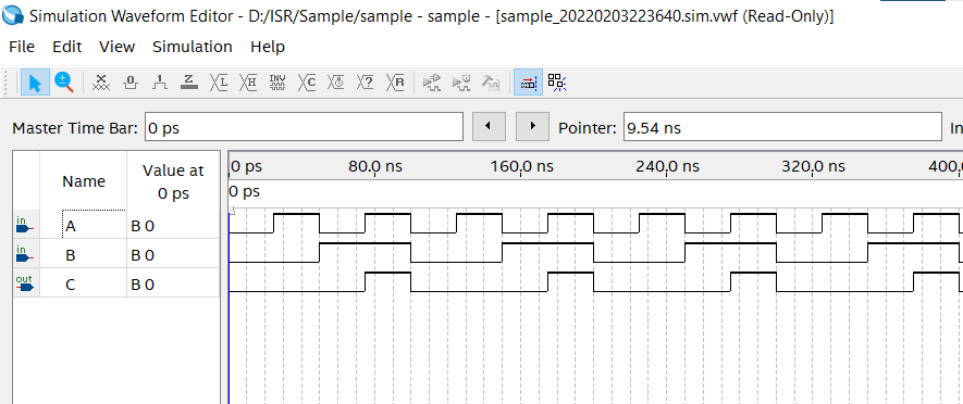
- Now the waveform editior will pop up and we can select the different logic levels and clocks.
- In below we have selected clock with different periods for analizing the possible output.
- Now click on the
simulation --> Run Functional SImulation.
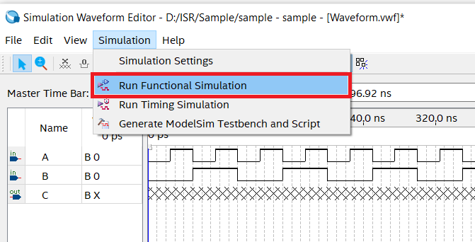
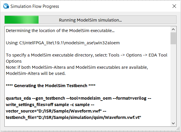
- After that a
simulation flow windowwill pop up and after that the output window will be shown.
ModelSim

We are using EDA(Electronic Design Automation) tools like ModelSim for the simulation of our logic. There are lots of other simulatiors are avalable in internet for velidating and checking the HDL descriptions.
Verilog is independent of this tools so there will be same output in all the simulatators but at the time of implimentation there will be different RTL design based on the compney whose implimentation tool we are using.
ModelSim comes with different edition like Intel, Xilinxs and Professional edition which is independent edition so there willl not be any inbuilt support for FPGA libraries for different kind of boards.
In HDL, Verilog will not need any library but VHDL will require atleast one library called IEEE library.
- In ModelSim there is 2 type of system we can use.
- GUI
- Command Based(Through
transcriptwindow)
ModelSim is having proprietary representation of HDL which is being written by programmer. It will try to replicate how things will actually work while working with the simulation.
- Simulation Guide: