Notes
Microprocessors
These are my notes on 8086 Microcontroller
Introduction to the Microprocessor and Computer
The world’s first microprocessor, the Intel 4004, was a 4-bit microprocessor–programmable controller on a chip. It addressed a mere 4096, 4-bit-wide memory locations. The 4004 instruction set contained only 45 instructions. It was fabricated with the then-current state-of-the-art P-channel MOSFET technology that only allowed it to execute instructions at the slow rate of 50 KIPs (kilo-instructions per second). This was slow when compared to the 100,000 instructions executed per second by the 30-ton ENIAC computer in 1946. The main difference was that the 4004 weighed much less than an ounce. The main problems with this early microprocessor were its speed, word width, and memory size.
The 8085 Microprocessor
In 1977, Intel Corporation introduced an updated version of the 8080—the 8085. The 8085 was to be the last 8-bit, general-purpose microprocessor developed by Intel. Although only slightly more advanced than an 8080 microprocessor, the 8085 executed software at an even higher speed. An addition that took 2.0 μs (500,000 instructions per second on the 8080) required only 1.3 μs (769,230 instructions per second) on the 8085. The main advantages of the 8085 were its internal clock generator, internal system controller, and higher clock frequency. This higher level of component integration reduced the 8085’s cost and increased its usefulness.
The 16-bit microprocessor evolved mainly because of the need for larger memory systems. The popularity of the Intel family was ensured in 1981, when IBM Corporation decided to use the 8088 microprocessor in its personal computer. The 16-bit 8086 and 8088 provided 1M byte of memory.
The 80286 Microprocessor
The 80286 microprocessor (also a 16-bit architecture microprocessor) was almost identical to the 8086 and 8088, except it addressed a 16M-byte memory system instead of a 1M-byte system. The instruction set of the 80286 was almost identical to the 8086 and 8088, except for a few additional instructions that managed the extra 15M bytes of memory. The clock speed of the 80286 was increased, so it executed some instructions in as little as 250 ns (4.0 MIPs) with the original release 8.0 MHz version. Some changes also occurred to the internal execution of the instructions, which led to an eightfold increase in speed for many instructions when compared to 8086/8088 instructions.
The 32-Bit Microprocessor
Applications began to demand faster microprocessor speeds, more memory, and wider data paths. This led to the arrival of the 80386 in 1986 by Intel Corporation. The 80386 represented a major overhaul of the 16-bit 8086–80286 architecture. The 80386 was Intel’s first practical 32-bit microprocessor that contained a 32-bit data bus and a 32-bit memory address.
The 80386 was available in a few modified versions such as the 80386SX, which addressed 16M bytes of memory through a 16-bit data and 24-bit address bus, and the 80386SL/80386SLC, which addressed 32M bytes of memory through a 16-bit data and 25-bit address bus. An 80386SLC version contained an internal cache memory that allowed it to process data at even higher rates. In 1995, Intel released the 80386EX microprocessor. The 80386EX microprocessor is called an embedded PC because it contains all the components of the AT class personal computer on a single integrated circuit. The 80386EX also contains 24 lines for input/output data, a 26-bit address bus, a 16-bit data bus, a DRAM refresh controller, and programmable chip selection logic.
The 80486 Microprocessor.
In 1989, Intel released the 80486 microprocessor, which incorpo- rated an 80386-like microprocessor, an 80387-like numeric coprocessor, and an 8K-byte cache memory system into one integrated package. Although the 80486 microprocessor was not radi- cally different from the 80386, it did include one substantial change. The internal structure of the 80486 was modified from the 80386 so that about half of its instructions executed in one clock instead of two clocks. Because the 80486 was available in a 50 MHz version, about half of the instructions executed in 25 ns (50 MIPs). The average speed improvement for a typical mix of instructions was about 50% over the 80386 that operated at the same clock speed. Later versions of the 80486 executed instructions at even higher speeds with a 66 MHz double-clocked version (80486DX2). The double-clocked 66 MHz version executed instructions at the rate of 66 MHz, with memory transfers executing at the rate of 33 MHz. (This is why it was called a double-clocked microprocessor.) A triple-clocked version from Intel, the 80486DX4, improved the internal execution speed to 100 MHz with memory transfers at 33 MHz. Note that the 80486DX4 microprocessor executed instructions at about the same speed as the 60 MHz Pentium. It also contained an expanded 16K-byte cache in place of the standard 8K-byte cache found on earlier 80486 microprocessors. Advanced Micro Devices (AMD) has produced a triple-clocked version that runs with a bus speed of 40 MHz and a clock speed of 120 MHz. The future promises to bring microprocessors that internally execute instructions at rates of up to 10 GHz or higher.
Pentium II and Pentium Xeon Microprocessors
The Pentium II microprocessor (released in 1997) represents a new direction for Intel. Instead of being an integrated circuit as with prior ver- sions of the microprocessor, Intel has placed the Pentium II on a small circuit board. The main reason for the change is that the L2 cache found on the main circuit board of the Pentium was not fast enough to function properly with the Pentium II. On the Pentium system, the L2 cache oper- ates at the system bus speed of 60 MHz or 66 MHz. The L2 cache and microprocessor are on a circuit board called the Pentium II module. This onboard L2 cache operates at a speed of 133 MHz and stores 512K bytes of information. The microprocessor on the Pentium II module is actually Pentium Pro with MMX extensions.
8086
- 8086 does not have a RAM or ROM inside it. However, it has internal registers for storing intermediate and final results and interfaces with memory located outside it through the System Bus.
- It is a 16-bit Integer processor in a 40 pin, Dual Inline Packaged IC.
- The size of the internal registers(present within the chip) indicate how much information the processor can operate on at a time (in this case 16-bit registers) and how it moves data around internally within the chip, sometimes also referred to as the internal data bus.
- 8086 provides the programmer with 14 internal registers, each 16 bits or 2 Bytes wide.
Memory segmentation:
- To increase execution speed and fetching speed, 8086 segments the memory.
- It’s 20 bit address bus can address 1MB of memory, it segments it into 16 64kB segments.
- 8086 works only with four 64KB segments within the whole 1MB memory.
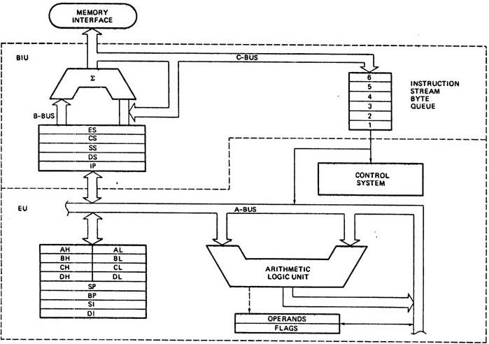
The internal architecture is divided into 2 units
- The Bus Interface Unit (BIU)
- The Execution Unit (EU)
1. The Bus Interface Unit (BIU)
- It provides the interface of 8086 to external memory and I/O devices via the System Bus. It performs various machine cycles such as memory read, I/O read etc. to transfer data between memory and I/O devices.
Role of BIU
- It generates the 20 bit physical address for memory access.
- It fetches instructions from the memory.
- It transfers data to and from the memory and I/O.
- Maintains the 6 byte prefetch instruction queue(supports pipelining).
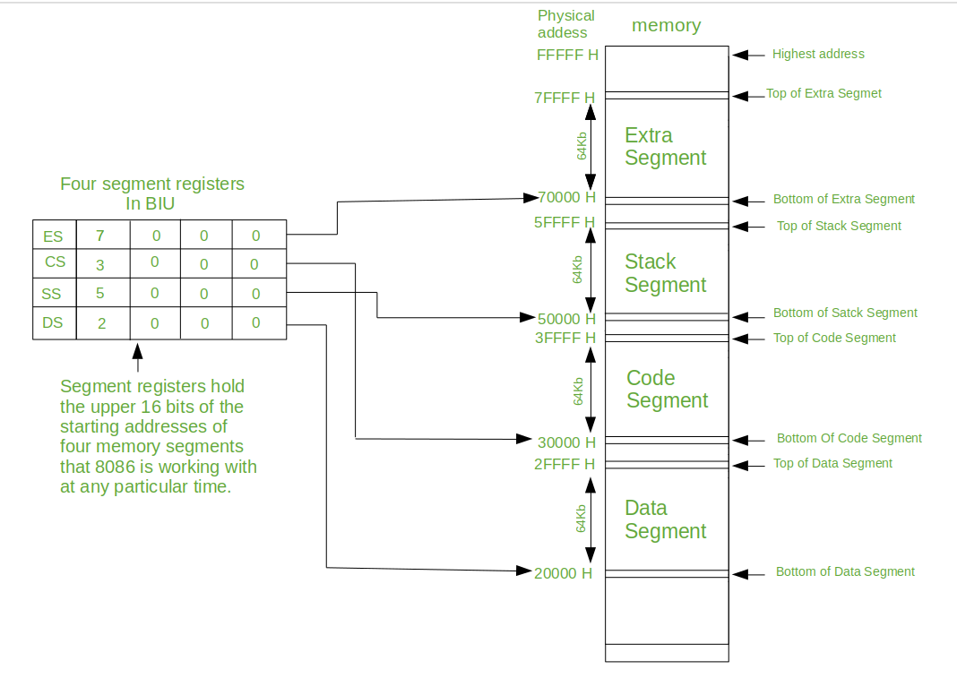
- BIU mainly contains the 4 Segment registers, the Instruction Pointer, a prefetch queue and an Address Generation Circuit
Instruction Pointer (IP):
- It is a 16 bit register. It holds offset of the next instructions in the Code Segment
- IP is incremented after every instruction byte is fetched.
- IP gets a new value whenever a branch instruction occurs.
- CS is multiplied by 10H to give the 20 bit physical address of the Code Segment.
- Address of the next instruction is calculated as CS x 10H + IP.
Example:
CS = 4321H
IP = 1000H
then CS x 10H = 43210H + offset =  44210H
Code Segment register
- CS holds the base address for the Code Segment.
- All programs are stored in the Code Segment and accessed via the IP(instruction pointer register).
- CS register cannot be modified by executing any instruction except branch instructions
Data Segment register
DS holds the base address for the Data Segment.
Stack Segment register
SS holds the base address for the Stack Segment.
Extra Segment register
ES holds the base address for the Extra Segment.
Address Generation Circuit:
- The BIU has a Physical Address Generation Circuit.
- It generates the 20 bit physical address using Segment and Offset addresses using the formula:
Physical Address = Segment Address x 10H + Offset Address
6 Byte Pre-fetch Queue
- It is a 6-byte FIFO RAM used to implement Pipelining.
- Fetching the next instruction (by BIU from CS) while executing the current instruction is called pipelining.
- BIU fetches the next "six instruction-bytes" from the Code Segment and stores it into the queue. Execution Unit (EU) removes instructions from the queue and executes them.
- The queue is refilled when atleast two bytes are empty as 8086 has a 16-bit data bus.
- Pipelining fails when a branch occurs, as the pre-fetched instructions are no longer useful. Hence as soon as 8086 detects a branch operation, it clears/discards the entire queue. Now, the next six bytes from the new location (branch address) are fetched and stored in the queue and Pipelining continues.
2. The Execution Unit (EU)
The main components of the EU are General purpose registers, the ALU, Special purpose registers, Instruction Register and Instruction Decoder and the Flag/Status Register.
- Fetches instructions from the Queue in BIU, decodes and executes arithmetic and logic operations using the ALU.
- Sends control signals for internal data transfer operations within the microprocessor.
- Sends request signals to the BIU to access the external module.
- It operates with respect to clock cycles (T-states) and not machine cycles.
- 8086 has four 16 bit general purpose registers AX, BX, CX and DX. Store intermediate values during execution. Each of these have two 8 bit parts (higher and lower).
AX register
It holds operands and results during multiplication and division operations. Also an accumulator during String operations.
BX register
It holds the memory address (offset address) in indirect addressing modes.
CX register
It holds count for instructions like loop, rotate, shift and string operations.
DX register
It is used with AX to hold 32 bit values during multiplication and division.
Arithmetic Logic Unit (16 bit)
Performs 8 and 16 bit arithmetic and logic operations.
Special purpose registers (16-bit)
- Stack Pointer(SP)
- Points to Stack top.
- Stack is in Stack Segment, used during instructions like PUSH, POP, CALL, RET etc.
- Base Pointer(BP)
- BP can hold offset address of any location in the stack segment.
- It is used to access random locations of the stack.
- Source Index(SI)
- It holds offset address in Data Segment during string operations.
- Destination Index(DI)
- It holds offset address in Extra Segment during string operations.
Instruction Register and Instruction Decoder
The EU fetches an opcode from the queue into the instruction register. The instruction decoder decodes it and sends the information to the control circuit for execution.
Flag/Status register (16 bits):
It has 9 flags that help change or recognize the state of the microprocessor.
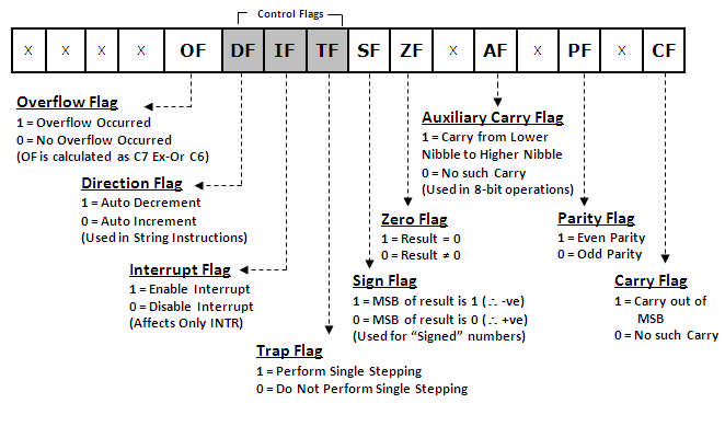
6 Status flags:
-
carry flag(CF) It is set whenever there is a carry {or borrow} out of the MSB of a the result (D7 bit for an 8-bit operation D15 bit for a 16-bit operation)
-
parity flag(PF) It is set if the result has even parity.
-
auxiliary carry flag(AF) It is set if a carry is generated out of the Lower Nibble. It is used only in 8-bit operations like DAA and DAS.
-
zero flag(Z) It is set if the result is zero.
-
sign flag(S) It is set if the MSB of the result is 1. For signed operations, such a number is treated as –ve.
-
overflow flag (O) It will be set if the result of a signed operation is too large to fit in the number of bits available to represent it. It can be checked using the instruction INTO (Interrupt on Overflow).
Status flags are updated after every arithmetic and logic operation.
3 Control flags:
-
trap flag(TF) It is used to set the Trace Mode i.e. start Single Stepping Mode. Here the µP is interrupted after every instruction so that, the program can be debugged.
-
interrupt flag(IF) It is used to mask (disable) or unmask (enable) the INTR interrupt.
-
direction flag(DF) If this flag is set, SI and DI are in auto-decrementing mode in String Operations.
These flags can be set or reset using control instructions like CLC, STC, CLD, STD, CLI, STI, etc
The Control flags are used to control certain operations.
References
- https://lambdageeks.com/8086-microprocessors-pin-diagram/
- https://www.geeksforgeeks.org/architecture-of-8086/
General purpose registers in 8086 microprocessor
General purpose registers are used to store temporary data within the microprocessor. There are 8 general purpose registers in 8086 microprocessor.
AX, BX, CX, DX are of 16 bits and is divided into two 8-bit registers XH and XL to also perform 8-bit instructions. SP, BP, SI, DI are of 16 bits and cannot be devided.
- AX
- This is the accumulator.
- It is generally used for arithmetical and logical instructions but in 8086 microprocessor it is not mandatory to have accumulator as the destination operand. Example:
ADD AX, AX //(AX = AX + AX)
- BX
- This is the base register.
- It is used to store the value of the offset. Example:
MOV BL, [500] (BL = 500H)
- CX
- This is the counter register.
- It is used in looping and rotation. Example:
MOV CX, 0005
LOOP
- DX
- This is the data register.
- It is used in multiplication an input/output port addressing. Example:
MUL BX (DX, AX = AX * BX)
- SP (stack pointer)
- It points to the topmost item of the stack.
- If the stack is empty the stack pointer will be (FFFE)H.
- Stack is in Stack Segment, used during instructions like PUSH, POP, CALL, RET etc.
- It’s offset address relative to stack segment.
- BP (base pointer)
- It is primary used in accessing parameters passed by the stack.
- It’s offset address relative to stack segment.
- SI (source index register)
- It is used in the pointer addressing of data and as a source in some string related operations.
- It’s offset is relative to data segment.
- DI (destination index register)
- It is used in the pointer addressing of data and as a destination in some string related operations.
- It’s offset is relative to extra segment.
1. Sign Flag (S)
- After any operation if the MSB (B(7)) of the result is 1, it indicates the number is negative and the sign flag becomes set, i.e. 1. If the MSB is 0, it indicates the number is positive and the sign flag becomes reset i.e. 0.
- from 00H to 7F, sign flag is 0
- from 80H to FF, sign flag is 1
- 1- MSB is 1 (negative)
- 0- MSB is 0 (positive)
Example:
MVI A 30 (load 30H in register A) MVI B 40 (load 40H in register B) SUB B (A = A – B) These set of instructions will set the sign flag to 1 as 30 – 40 is a negative number.
MVI A 40 (load 40H in register A) MVI B 30 (load 30H in register B) SUB B (A = A – B) These set of instructions will reset the sign flag to 0 as 40 – 30 is a positive number.
Zero Flag (Z) – After any arithmetical or logical operation if the result is 0 (00)H, the zero flag becomes set i.e. 1, otherwise it becomes reset i.e. 0. 00H zero flag is 1. from 01H to FFH zero flag is 0 1- zero result 0- non-zero result
Example:
MVI A 10 (load 10H in register A) SUB A (A = A – A) These set of instructions will set the zero flag to 1 as 10H – 10H is 00H
Auxiliary Carry Flag (AC) – This flag is used in BCD number system(0-9). If after any arithmetic or logical operation D(3) generates any carry and passes on to B(4) this flag becomes set i.e. 1, otherwise it becomes reset i.e. 0. This is the only flag register which is not accessible by the programmer 1-carry out from bit 3 on addition or borrow into bit 3 on subtraction 0-otherwise
Example:
MOV A 2B (load 2BH in register A) MOV B 39 (load 39H in register B) ADD B (A = A + B) These set of instructions will set the auxiliary carry flag to 1, as on adding 2B and 39, addition of lower order nibbles B and 9 will generate a carry.
Parity Flag (P) – If after any arithmetic or logical operation the result has even parity, an even number of 1 bits, the parity register becomes set i.e. 1, otherwise it becomes reset i.e. 0. 1-accumulator has even number of 1 bits 0-accumulator has odd parity
Example:
MVI A 05 (load 05H in register A) This instruction will set the parity flag to 1 as the BCD code of 05H is 00000101, which contains even number of ones i.e. 2.
Carry Flag (CY) – Carry is generated when performing n bit operations and the result is more than n bits, then this flag becomes set i.e. 1, otherwise it becomes reset i.e. 0. During subtraction (A-B), if A>B it becomes reset and if (A<B) it becomes set. Carry flag is also called borrow flag. 1-carry out from MSB bit on addition or borrow into MSB bit on subtraction 0-no carry out or borrow into MSB bit
Example:
MVI A 30 (load 30H in register A) MVI B 40 (load 40H in register B) SUB B (A = A – B) These set of instructions will set the carry flag to 1 as 30 – 40 generates a carry/borrow.
MVI A 40 (load 40H in register A) MVI B 30 (load 30H in register B) SUB B (A = A – B) These set of instructions will reset the sign flag to 0 as 40 – 30 does not generate any carry/borrow.
Overflow Flag (O) – This flag will be set (1) if the result of a signed operation is too large to fit in the number of bits available to represent it, otherwise reset (0). After any operation, if D[6] generates any carry and passes to D[7] OR if D[6] does not generates carry but D[7] generates, overflow flag becomes set, i.e., 1. If D[6] and D[7] both generate carry or both do not generate any carry, then overflow flag becomes reset, i.e., 0. Example: On adding bytes 100 + 50 (result is not in range -128…127), so overflow flag will set.
MOV AL, 50 (50 is 01010000 which is positive) MOV BL, 32 (32 is 00110010 which is positive) ADD AL, BL (82 is 10000010 which is negative) Overflow flag became set as we added 2 +ve numbers and we got a -ve number.
(b) Control Flags – The control flags enable or disable certain operations of the microprocessor. There are 3 control flags in 8086 microprocessor and these are:
Directional Flag (D) – This flag is specifically used in string instructions. If directional flag is set (1), then access the string data from higher memory location towards lower memory location. If directional flag is reset (0), then access the string data from lower memory location towards higher memory location. Interrupt Flag (I) – This flag is for interrupts. If interrupt flag is set (1), the microprocessor will recognize interrupt requests from the peripherals. If interrupt flag is reset (0), the microprocessor will not recognize any interrupt requests and will ignore them. Trap Flag (T) – This flag is used for on-chip debugging. Setting trap flag puts the microprocessor into single step mode for debugging. In single stepping, the microprocessor executes a instruction and enters into single step ISR. If trap flag is set (1), the CPU automatically generates an internal interrupt after each instruction, allowing a program to be inspected as it executes instruction by instruction. If trap flag is reset (0), no function is performed.
Memory Segmentation in 8086
Concept of Segmentation
-
Segmentation means dividing the memory into logically different parts called segments.
-
8086 has a 20-bit address bus, hence it can access 2^20 Bytes i.e. 1MB memory.
-
But this also means that Physical address will now be 20 bit. It is not possible to work with a 20 bit address as it is not a byte compatible number. (20 bits is two and a half bytes). To avoid working with this incompatible number, we create a virtual model of the memory.
-
Here the memory is divided into 4 segments: Code, Stack Data and Extra.
-
The max size of a segment is 64KB and the minimum size is 16 bytes.
-
Now programmer can access each location with a VIRTUAL ADDRESS.
-
The Virtual Address is a combination of Segment Address and Offset Address.
-
Segment Address indicates where the segment is located in the memory (base address)
-
Offset Address gives the offset of the target location within the segment.
-
Since both, Segment Address and Offset Address are 16 bits each, they both are compatible numbers and can be easily used by the programmer.
-
Moreover, Segment Address is given only in the beginning of the program, to initialize the segment. Thereafter, we only give offset address.
-
Hence we can access 1 MB memory using only a 16 bit offset address for most part of the program. This is the advantage of segmentation.
-
Moreover, dividing Code, stack and Data into different segments, makes the memory more organized and prevents accidental overwrites between them.
-
The Maximum Size of a segment is 64KB because offset addresses are of 16 bits. 216 = 64KB.
-
As max size of a segment is 64KB, programmer can create multiple Code/Stack/Data segments till the entire 1 MB is utilized, but only one of each type will be currently active.
-
The physical address is calculated by the microprocessor, using the formula:
PHYSICAL ADDRESS = SEGMENT ADDRESS X 10H + OFFSET ADDRESS Ex: if Segment Address = 1234H and Offset Address is 0005H then Physical Address = 1234H x 10H + 0005H = 12345H -
This formula automatically ensures that the minimum size of a segment is 10H bytes (10H = 16 Bytes).
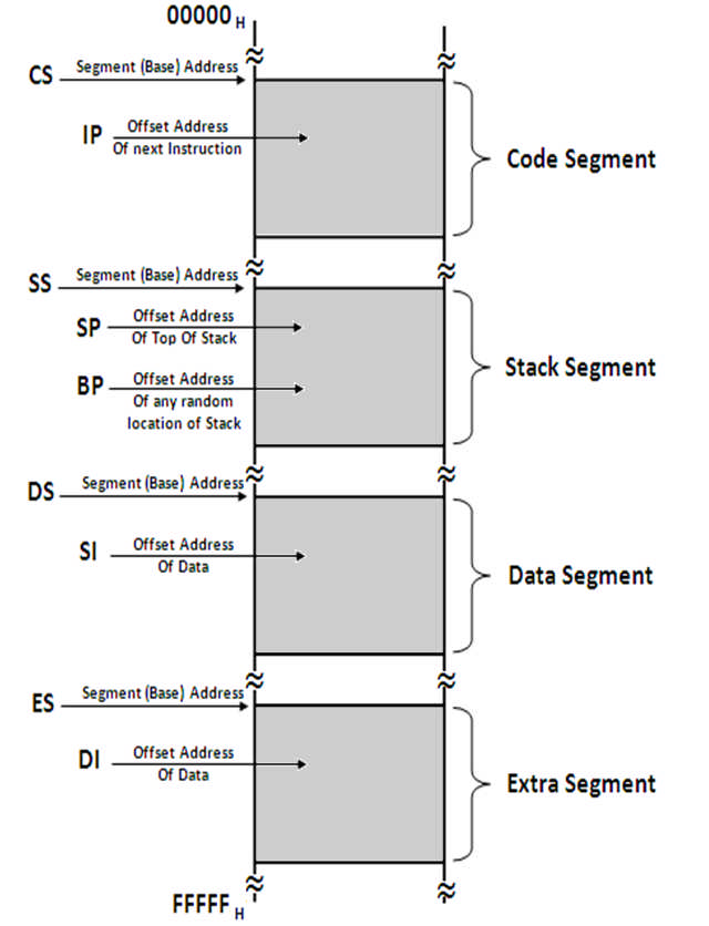
Code Segment
- This segment is used to hold the program to be executed.
- Instruction are fetched from the Code Segment.
- CS register holds the 16-bit base address for this segment.
- IP register (Instruction Pointer) holds the 16-bit offset address.
Data Segment
- This segment is used to hold general data.
- This segment also holds the source operands during string operations.
- DS register holds the 16-bit base address for this segment.
- BX register is used to hold the 16-bit offset for this segment.
- SI register (Source Index) holds the 16-bit offset address during String Operations.
Stack Segment
- This segment holds the Stack memory, which operates in LIFO manner.
- SS holds its Base address.
- SP (Stack Pointer) holds the 16-bit offset address of the Top of the Stack.
- BP (Base Pointer) holds the 16-bit offset address during Random Access.
Extra Segment
- This segment is used to hold general data.
- Additionally, this segment is used as the destination during String Operations.
- ES holds the Base Address.
- DI holds the offset address during string operations.
Learning Objective
- Learn and appreciate computer architecture with an emphasis on system design, performance and analysis.
- Elevate thinking process to the level of performance improvement techniques for recent multi-core architectures.
- Understand and analyze events happening at hardware level with the help of open source simulators.
- Enable exploration of future directions in computer architecture research.
Focus
- Part A: Processor design trends - instruction pipeline concepts, pipeline hazards, out-of-order execution, static and dynamic scheduling, advanced branch prediction techniques, multiple issue superscalar processors, vector and GPU architectures.
- Part B: Cache memory concepts and optimization techniques, DRAM organization, memory controllers. Many-core processors; principles, design concepts and microarchitecture of NoC.
- Part C: Exploration in system design and analysis with the help of open source architecture simulator GEM5
Abstraction of Modern Computer Architecture
- Application
- Algorithm
- Programming Language
- Operating System/Virtual Machines
- Instruction Set Architecture
- Microarchitectwre
- Register-Transfer Level
- Gates
- Circuits
- Devices
- Physics
-
ISA vs Microarchitecture
-
ISA Characteristics
- Machine Models
- Encoding
- Data Types
- Instructions
- Addressing Modes
For each operation that is to be carried out with respect to an instruction, we have multiple sub operations like instruction fetch, decode, operand fetch, result store and next instruction.
Instruction Execution Cycle
- Instruction Fetch - Obtain instruction from program storage
- Instruction Decode - Determine required actions and instruction size
- Operand Fetch - Locate and obtain operand data
- Execute - Compute result value or status
- Result Store - Deposit results in storage for later use
- Next Instruction - Determine successor instruction
Processor Memory Interaction
If the processor wants to fetch an instruction, the first thing that you have to do is the address of the instruction which is available in the program counter has to be transferred to a MAR. Similarly, if processor wanted to read or write any data into memory, then also the address has to be kept inside MAR. So MAR is a register which is known as memory address register, which contains the address of the next word that has to be accessed in the memory.
It can be either for a read or a fetch operation or it can be for a right operation. Now whatever is the address that is placed in MAR, the data contents are being exchanged through MDR. So, if it is a write operation, then the contents in MDR are transferred to memory on a location specified by MAR. If it is for an instruction fetch or a read operation, then the contents of the designated location specified by MAR are being transferred to the processor and it reaches MDR first.
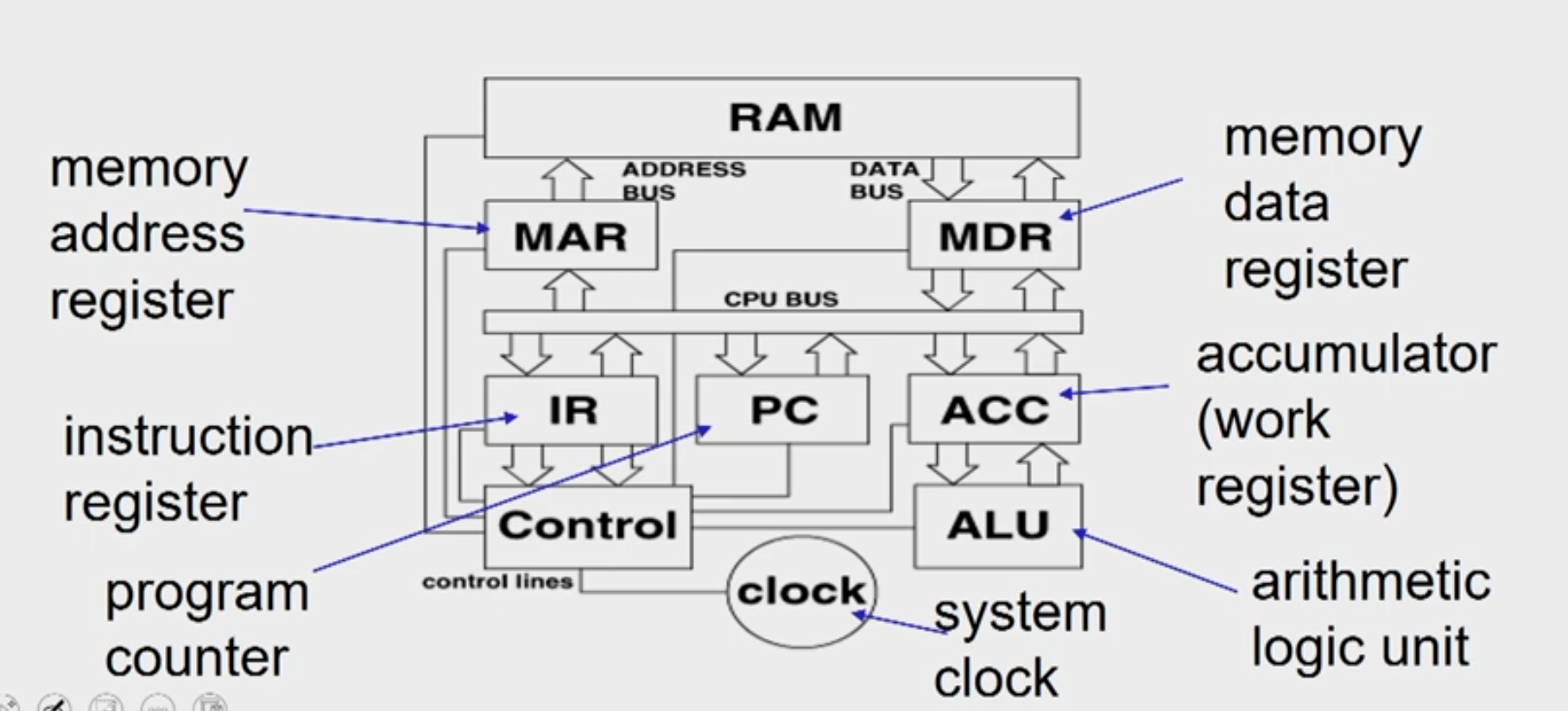
Instruction FETCH
- address of the next instruction is transferred from PC to MAR
- the instruction is located in memory
- instruction is copied from memory to MDR
- instruction is transferred to and decoded in the IR
- control unit sends signals to appropriate devices to cause execution of the instruction
Memory Address Decoder
Byte Ordering
- Little Endian
- Big Endian
Byte Alignment
Data alignment
Data alignment means putting the data in memory at address equal to some multiple of the word size. This increases the performance of system due to the way the CPU handles memory.
Data Structure Padding Now, to align the data, it may be necessary to
insert some extra bytes between the end of the last data structure and the start of the next data structure as the data is placed in memory as multiples of fixed word size. This insertion of extra bytes of memory to align the data is called data structure padding.
Types of operations
Arithmetic and Logical Operations
- integer arithmetic
- comparing two quantities
- shifting, rotating bits in a quantity
- testing, comparing, and converting bits
Data Movement Operations
- moving data from memory to the CPU
- moving data from memory to memory
- input and output
Program Control Operations
- starting a program
- halting a program
- skipping to other instructions
- testing data to decide whether to skip over some instructions
Instruction Set Architecture Multiple instructions combined together to form
program and multiple programs combined together to form software which will basically is a big task.
Opcode specifies what needs to be done operand specifies where it needs to be done. And the set of all possible instruction that a processor can do it is known as instruction set architecture.
Classification of ISA
Stack
- Accumulator
- Register-memory
- Register-register / load-store
Addressing Modes
- Register add r1, r2 r1 <- rl+r2
- Immediate add r1, #5 r1 <- r1+5
- Direct add r1, (0x200) r1 <- r1+M[0x200]
- Register indirect add r1, (r2) r1 <- r1+M[r2]
- Displacement add r1, 100(r2) r1 <- r1+M[r2+100]
- Indexed add r1, (r2+r3) r1 <- r1+M[r2+r3])
- Scaled add r1, (r2+r34) r1 <- r1+M[(r2+r34]
- Memory indirect add r1, @(r2) r1 <- r1+M[M[r2]]
- Auto-increment add r1, (r2)+ r1 <- r1+M[r2], r2++
- Auto-decrement add r1, -(r2) r2--, r1 <- r1+M[r2]
Architecture vs. Microarchitecture
“Architecture”/Instruction Set Architecture:
- Programmer visible state (Memory & Register)
- Operations (Instructions and how they work)
- Execution Semantics (interrupts)
- Input/Output
- Data Types/Sizes
Microarchitecture/Organization:
- Tradeoffs on how to implement ISA for some metric (Speed, Energy, Cost)
- Examples: Pipeline depth, number of pipelines, cache size, silicon area, peak power, execution ordering, bus widths, ALU widths
Why the Diversity in ISAs? Technology Influenced ISA
- Storage is expensive, tight encoding important
- Reduced Instruction Set Computer
- Remove instructions until whole computer fits on die
- Multicore/Manycore
- Transistors not turning into sequential performance
Application Influenced ISA
- Instructions for Applications
- DSP instructions
- Compiler Technology has improved
- SPARC Register Windows no longer needed
- Compiler can register allocate effectively
When can we say one computer / architecture / design is better than others?
- Desktop PC (execution time of a program)
- Server (transactions / unit time)
When can we say X is n times fasterthanY ?
- Execution time(y) / Execution time(x) =n
- Throughput(x) / Throughput(y) = n
Typical performance metrics
- Response time - When a request is coming from a machine to another machine, the time for the second machine to respond to that request is known as response time
- Throughput - Number of task that is completed in a unit time
- CPU time - Total time associated with respect to a program in cpu execution
- Wall clock time - Actual time taken for a program to execute ie sum total of cpu time and non-cpu time(peripheral time)
- Speedup - If the execution time of one is larger than other then it means speedup
Benchmarks
- Toy programs (e.g. sorting, matrix multiply)
- Synthetic benchmarks (e.g. Dhrystone)
- Benchmark suites (e.g. SPEC06, SPLASH)
SPECRatio
SPECRatio(A) = Execution time(reference) / Execution time(A)
Reference for SPEC 2006: Sun Ultra Enterprise 2 workstation with a 296-MHz UltraSPARC II processor
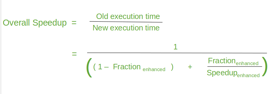
Amdhal's Law
- Amdahl’s Law defines the speedup that can be gained by improving some portion of a computer.
- The performance improvement to be gained from using some faster mode of execution is limited by the fraction of the time the faster mode can be used.
Example
Suppose that we want to enhance the floating point operations of a processor by introducing a new advanced FPU unit. Let the new FPU is 10 times faster on floating point computations than the original processor. Assuming a program has 40% floating point operations, what is the overall speedup gained by incorporating the enhancement?
Solution:
- Fraction enhanced = 0.4
- Speedup enhanced = 10
- Therefore speedup = 1/(0.6 + 0.4/10) = 1.56 times faster
Example
A common transformation required in graphics processors is square root. Implementations of floating-point (FP) square root vary significantly in performance, especially among processors designed for graphics. Suppose FP square root (FPSQR) is responsible for 20% of the execution time of a critical graphics benchmark.
One proposal is to enhance the FPSQR hardware and speed up this operation by a factor of 10. The other alternative is just to try to make all FP instructions in the graphics processor run faster by a factor of 1.6; FP instructions are responsible for half of the execution time for the application. Compare these two design alternatives using Amdahl's Law.
Solution:
- Case A: FPSQR hardware optimization
- S = 1.219
- Case B: FP instructions optimization
- S = 1.23
Principles of Computer Design
- All processors are driven by clock.
- Expressed as clock rate in GHz or clock period in ns
- CPU Time = CPU clock cycles x clock cycle time
CPl = CPU clock cycles for a program / Instruction Count CPU Time = IC * CPI * CCT
- Clock cycle time- hardware technology
- CPI- Organization and ISA
- IC-ISA and compiler technology
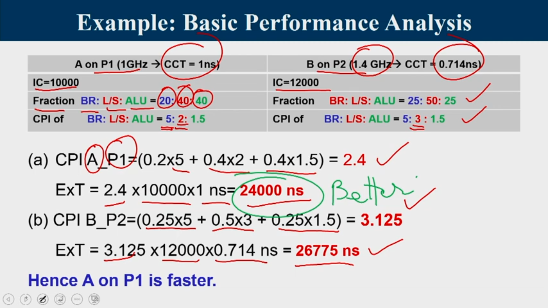
Example: Basic Performance Analysis
Consider two programs A and B that solves a given problem. A is scheduled to run on a processor P1 operating at 1 GHz and B is scheduled to run on processor P2 running at 1.4 GHz. A has total 10000 instructions, out of which 20% are branch instructions, 40% load store instructions and rest are ALU instructions. B is composed of 25% branch instructions. The number of load store instructions in B is twice the count of ALU instructions. Total instruction count of B is 12000. In both P1 and P2 branch instructions have an average CPI of 5 and ALU instructions has an average CPI of 1.5. Both the architectures differ in the CPI of load-store instruction. They are 2 and 3 for P1 and P2, respectively. Which mapping (A on P1 or B on P2) solves the problem faster, and by how much?
Amdahl's Law
A company is releasing 2 latest versions (beta and gamma) of its basic processor architecture named alpha. Beta and gamma are designed by making modifications on three major components (X, Y and Z) of the alpha. It was observed that for a program A the fractions of the total execution time on these three components, X, Y, and Z are 40%, 30%, and 20%, respectively. Beta speeds up X and Z by 2 times but slows down Y by 1.3 times, where as gamma speeds up X, Y and Z by 1.2, 1.3 and 1.4 times, respectively. a. How much faster is gamma over alpha for running A? b. Whether beta or gamma is faster for running A? Find the speedup factor
Solution: a. Gamma is 1.239 times faster over alpha b. Beta is faster than gamma -> 1.267/1.239 = 1.022 times
Introduction to MIPS
- Microprocessor without Interlocked Pipelined Stages
- 32 registers (32 bit each)
- Uniform length instructions
- RISC- Load store architecture
Advantages of MIPS
- It is easy to understand and measure
- It helps in calculation of CPU processor speed (cycles per second), CPI (average clock cycles per instruction) and Execution time.
- It handles when amount of work is large.
Disadvantages of MIPS
- It may not reflect real execution, since simple instructions do way better.
- It is an older, obsolete measure of a computer’s speed and power
Instruction Representation
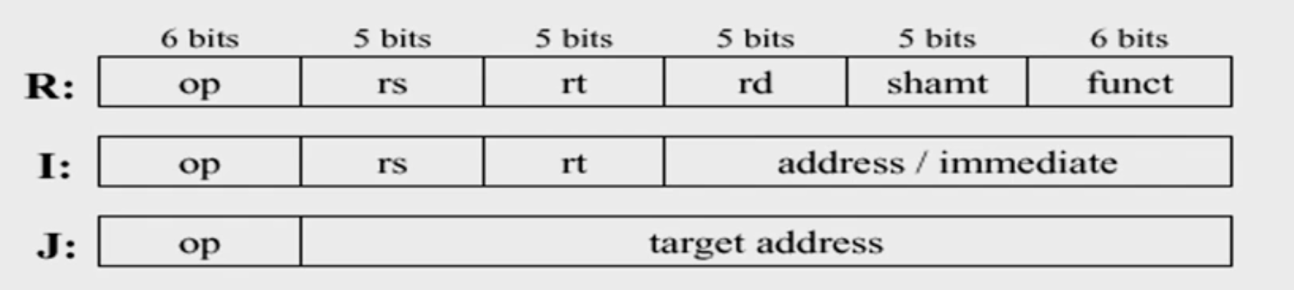
- op: basic operation of the instruction (opcode)
- rs: first source operand register
- rt: second source operand register
- rd: destination operand register
- shamt: shift amount
- funct: selects the specific variant of the opcode (function code)
- address: offset for load/store instructions (+/-2^15)
- immediate: constants for immediate instructions
R = Register type instruction
Pipeline Characteristics
- Pipelining doesn't reduce latency of single task, it improves throughput of entire workload
- Pipeline rate limited by slowest pipeline stage
- Potential speedup = Number of pipe stages
- Unbalanced lengths of pipe stages reduces speedup
- Time to fill pipeline and time to drain it reduces speedup
Pipeline in Circuits
- Pipelining partitions the system into multiple independent stages with added buffers between the stages.
- Pipelining can increase the throughout of a system.
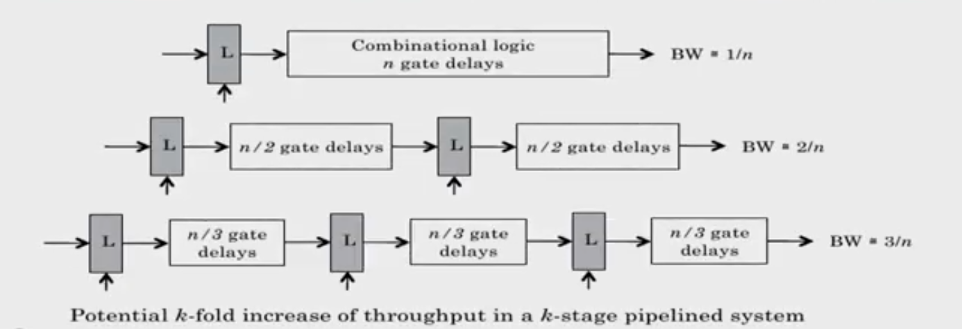
Dividing the actual circuit which was n-logic gates into smaller sub components and to interface with them with latches is called pipelining inside the circuits
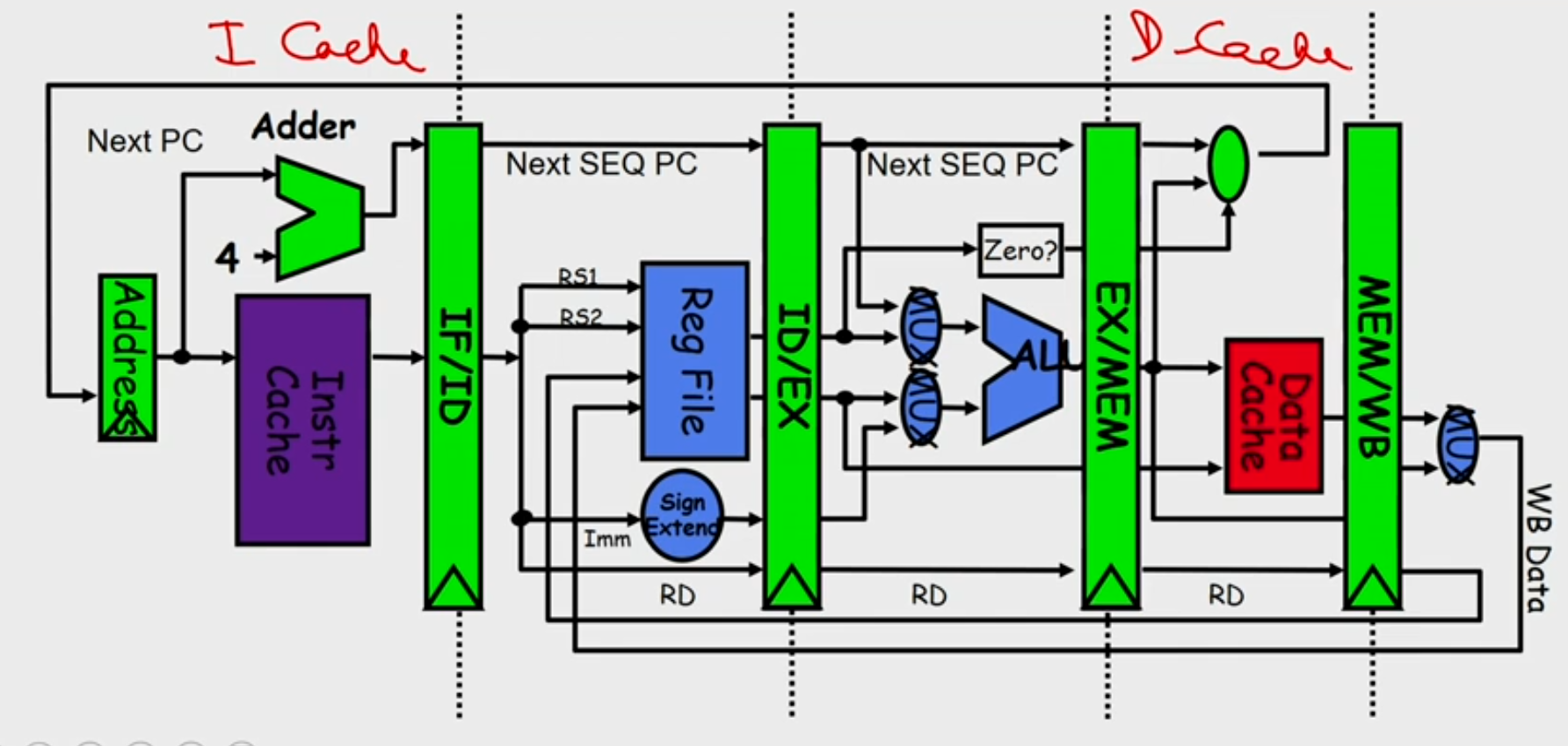
Pipeline in MIPS
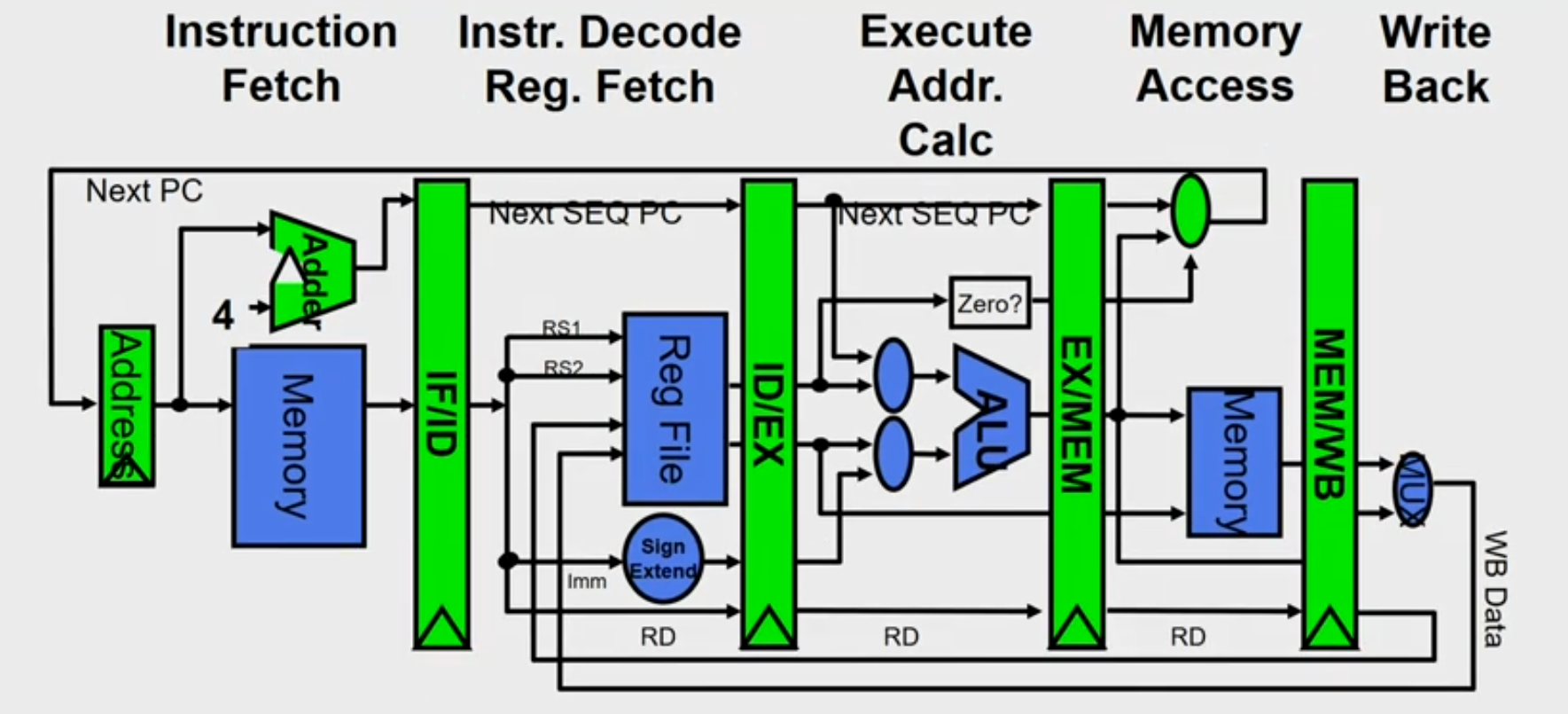
- Each instruction can take at most 5 clock cycles
- Instruction fetch cycle (IF)
- Based on PC, fetch the instruction from memory
- Increment PC
- Instruction decode/register fetch cycle (ID)
- Decode the instruction + register read operation
- Fixed field decoding
- Ex: [ADD R1,R2,R3] : A3.01.02.03
- 10100011 00000001 00000010 00000011
- Ex: [LW R1,8(R2)] : 86.01.02.03
- 10000110 00000001 00001000 00000010
- Equality check of registers
- Computation of branch target address if any
- Execution/Effective address cycle (EX)
- Memory reference: Calculate the effective address
- [LW R1,8(R2)] Effective ADDR= [R2] +8
- Register-register ALU instruction
- [ADD R1,R2,R2] Actual execution ie R2+R3
- Register-immediate ALU instruction
- Memory access cycle (MEM)
- Load instruction: Read from memory using effective address [LW R1,8(R2)]
- Store instruction: Write the data in the register to memory using effective address [SW R3,16(R4)]
- Write-back cycle (WB)
-
Register-register ALU instruction or load instruction
-
Write the result to register file [LW R1,8(R2)], [ADD R1,R2,R3]
-
Cycles required to implement different instructions
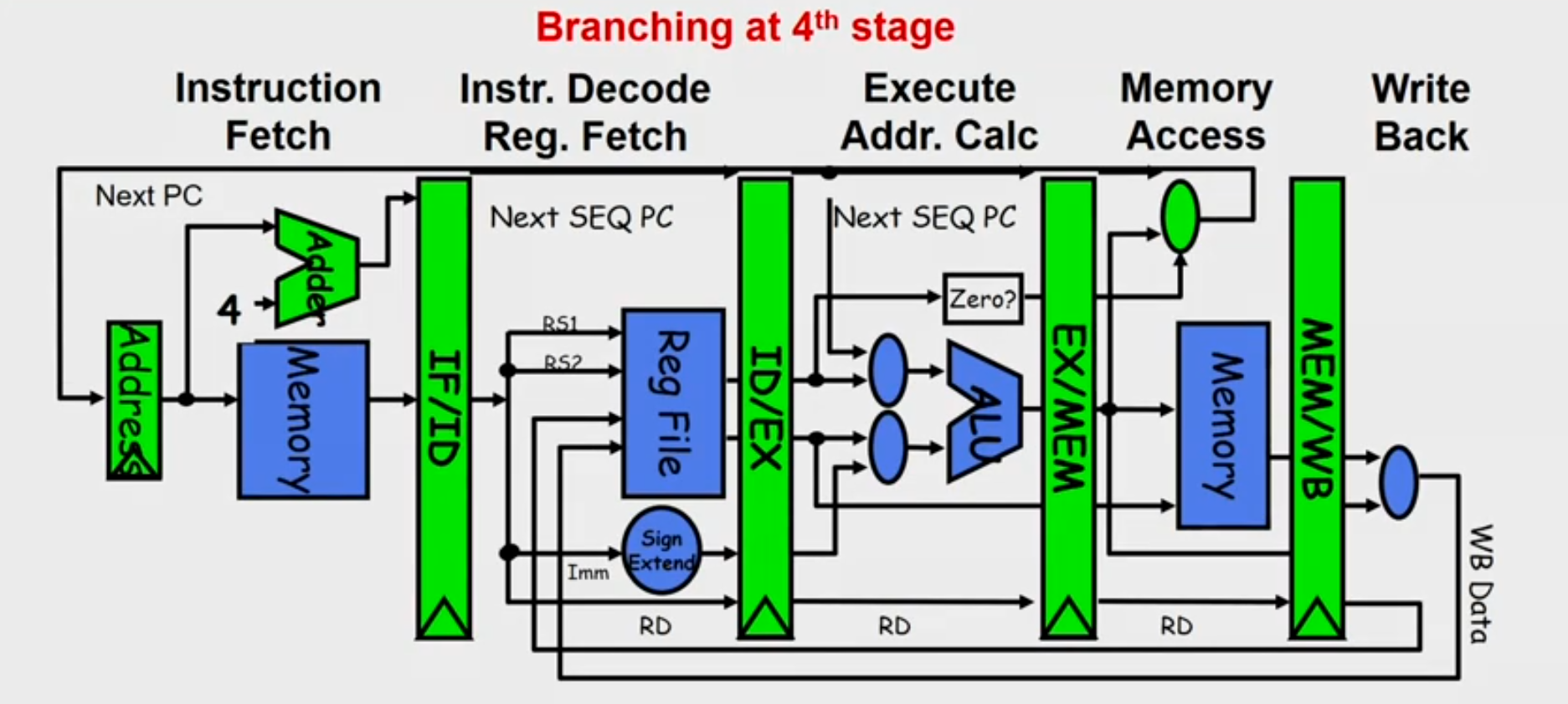
- Branch instructions — 4 cycles
- Store instructions — 4 cycles
- All other instructions — 5 cycles
Pipeline Issues
-
Ideal Case: Uniform sub-computations
- The computation to be performed can be evenly partitioned into uniform-latency sub-computations
-
Reality: Internal fragmentation
- Not all pipeline stages may have the uniform latencies
-
Impact of ISA
- Memory access is a critical sub-computation
- Memory addressing modes should be minimized
- Fast cache memories should be employed
-
Ideal Case : Identical computations
- The same computation is to be performed repeatedly on a large number of input data sets
-
Reality: External fragmentation
- Some pipeline stages may not be used
-
Impact of ISA
- Reduce the complexity and diversity of the instruction types
- RISC architectures use uniform stage simple instructions
-
Ideal Case : Independent computations
- All the instructions are mutually independent
-
Reality: Pipeline stalls - cannot proceed
- A later computation may require the result of an earlier computation
-
Impact of ISA
- Reduce Memory addressing modes - dependency detection
- Use register addressing mode - easy dependencies check
Pipeline Hazards
- Hazards: circumstances that would cause incorrect execution if next instruction is fetched and executed
- Structural hazards: Different instructions, at different stages, in the pipeline want to use the same hardware resource
- Data hazards: An instruction in the pipeline requires data to be computed by a previous instruction still in the pipeline
- Control hazards: Succeeding instruction, to put into pipeline, depends on the outcome of a previous branch instruction, already in pipeline
Structural Hazard
-
Eliminate the use same hardware for two different things at the same time
-
Solution 1: Wait
- must detect the hazard
- must have mechanism to stall
-
Solution 2: Duplicate hardware
- Multiple such units will help both instruction to progress
- Multiple such units will help both instruction to progress
Data Hazard
Read After Write(RAW)
- Instr-2 tries to read operand before Instr-1, writes it
Instr-1: add r1,r2,r3
Instr-2: sub r4,r1,r3
Write After Read (WAR)
- Instr-2, writes operand before Instr-1, reads it
Instr-1: sub r4,r1,r3 Instr-2: add r1,r2,r3 Instr-3: mul r6,r1,r7 - Called an anti-dependence by compiler writers.
- This results from reuse of the name r1
- Can’t happen in MIPS 5 stage pipeline because:
- All instructions take 5 stages, and
- Reads are always in stage 2, and
- Writes are always in stage 5
Write After Write (WAW)
- Instr-2, writes operand before Instr-1, writes it.
Instr-1: sub r1,r4,r3 Instr-2: add r1,r2,r3 Instr-3: mul r6,r1,r7 - Called an output dependence
- This also results from the reuse of name r1
- Can’t happen in MIPS 5 stage pipeline because:
- All instructions take 5 stages, and
- Writes are always in stage 5
- WAR and WAW happens in out of order pipes
Handle Data hazards
- Data hazard: instruction needs data from the result of a previous instruction still executing in pipeline
- Solution: Forward data if possible
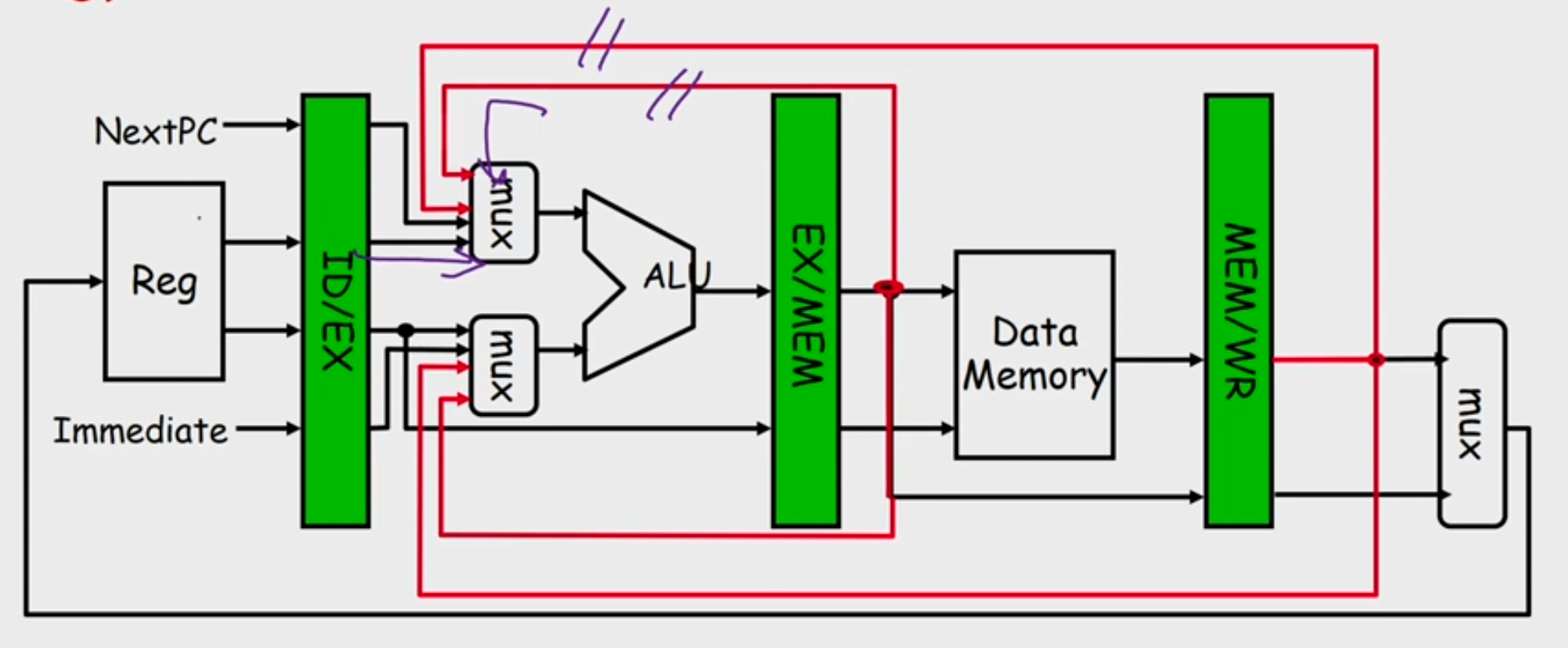
- Load ALU Hazard
- Solution: Delay the next instruction (add bubble)
- Software Solution: Arrange the instructions while compiling to avoid hazard
Control Hazard
- Normal MIPS Pipeline
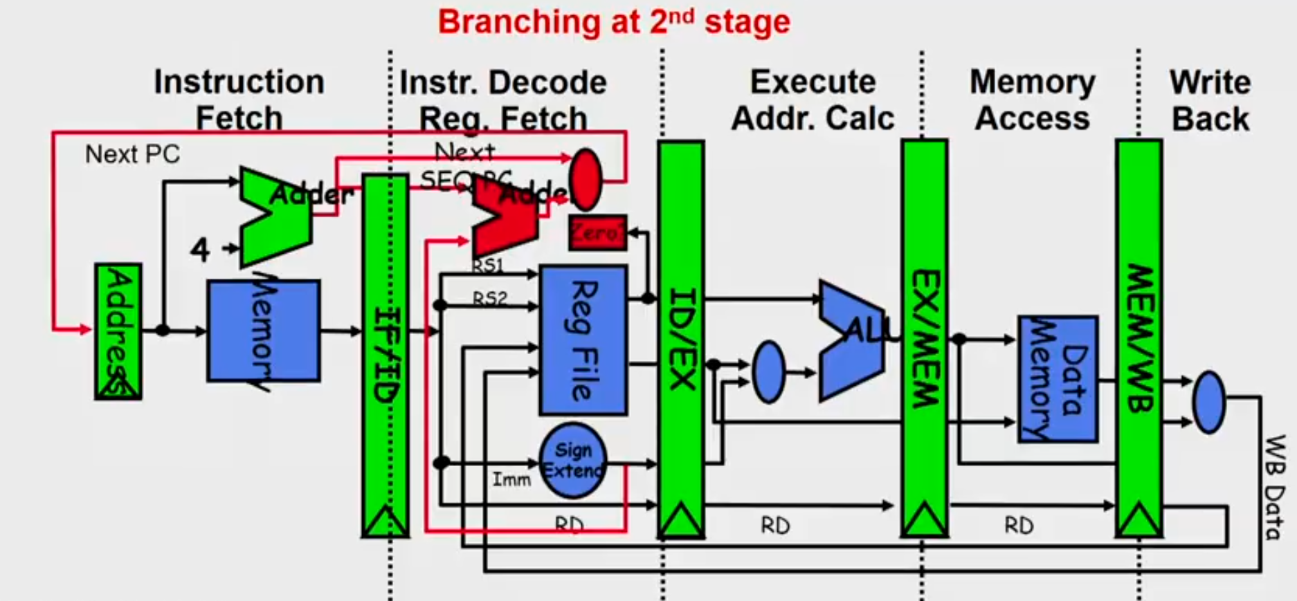
- Modern MIPS Pipeline
Four Branch Hazard Alternatives
1: Stall until branch direction is clear
2: Predict Branch Not Taken
- Execute successor instructions in sequence
- "Squash" instructions in pipeline if branch actually taken
3: Predict Branch Taken
- But branch target address in is not known by IF stage
- Target is known at same time as branch outcome (IDstage)
- MIPS still incurs 1 cycle branch penalty
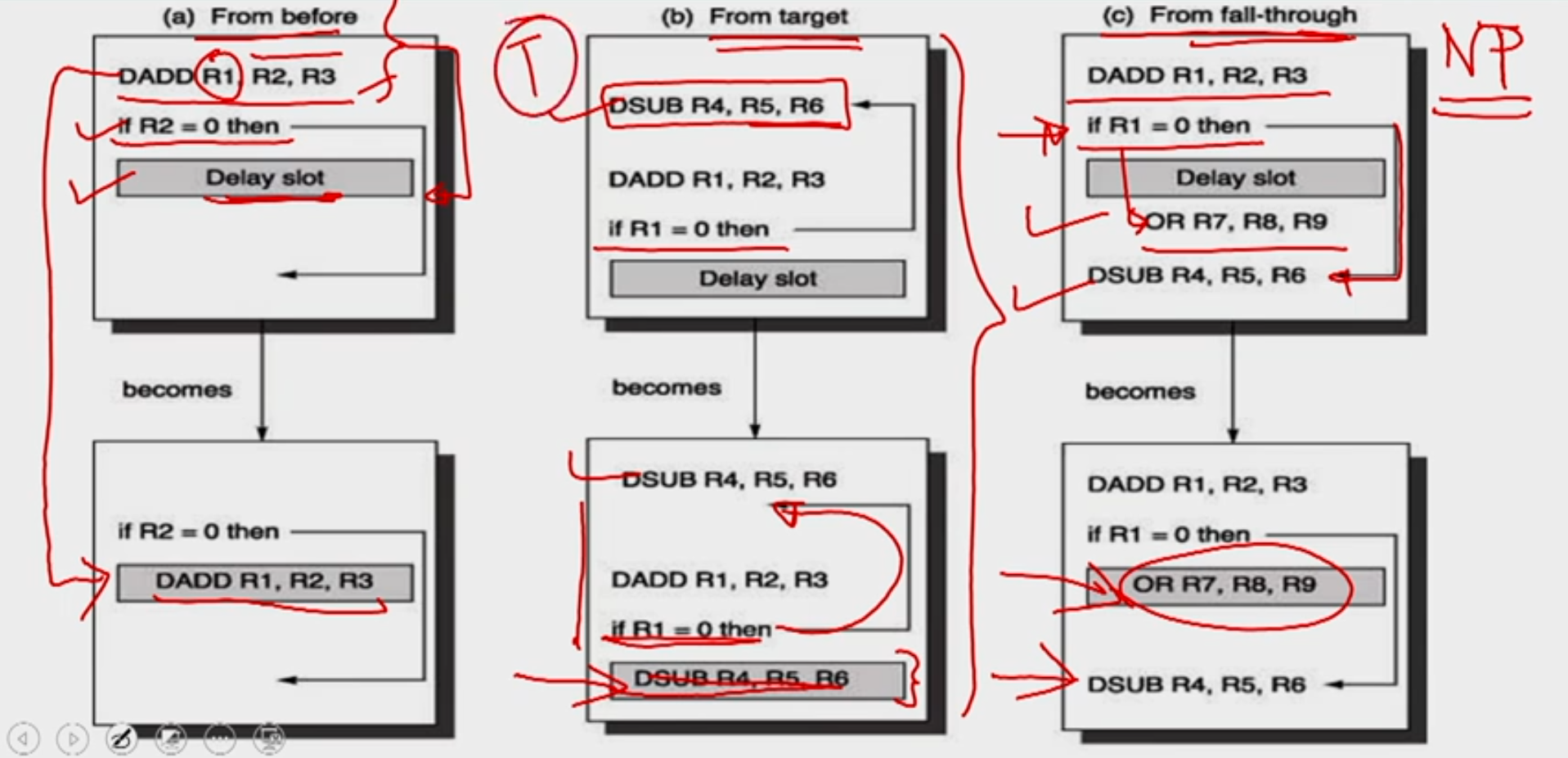
4: Delayed Branch
- Define branch to take place AFTER one instruction following the branch instruction
- 1 slot delay allows proper decision and branch target address in 5 stage pipeline (MIPS uses this approach)
- Where to get instructions to fill branch delay slot?
Conditional Branches
- When do you know you have a branch?
- During ID cycle (Could you know before that?)
- When do you know if the branch is Taken or Not-Taken
- During EXE cycle/ ID stage depending on the design
- We need for sophisticated solutions for following cases
- Modern pipelines are deep ( 10 + stages)
- Several instructions issued/cycle
- Several predicted branches in-flight at the same time
Dynamic branch prediction
-
Execution of a branch requires knowledge of:
-
Branch instruction - encode whether instruction is a branch or not. Decide on taken or not taken (i.e., prediction can be done at IF stage)
-
Whether the branch is Taken/Not-Taken (hence a branch prediction mechanism)
-
If the branch is taken what is the target address (can be computed but can also be "precomputed", i.e., stored in some table)
-
If the branch is taken what is the instruction at the branch target address (saves the fetch cycle for that instruction)
-
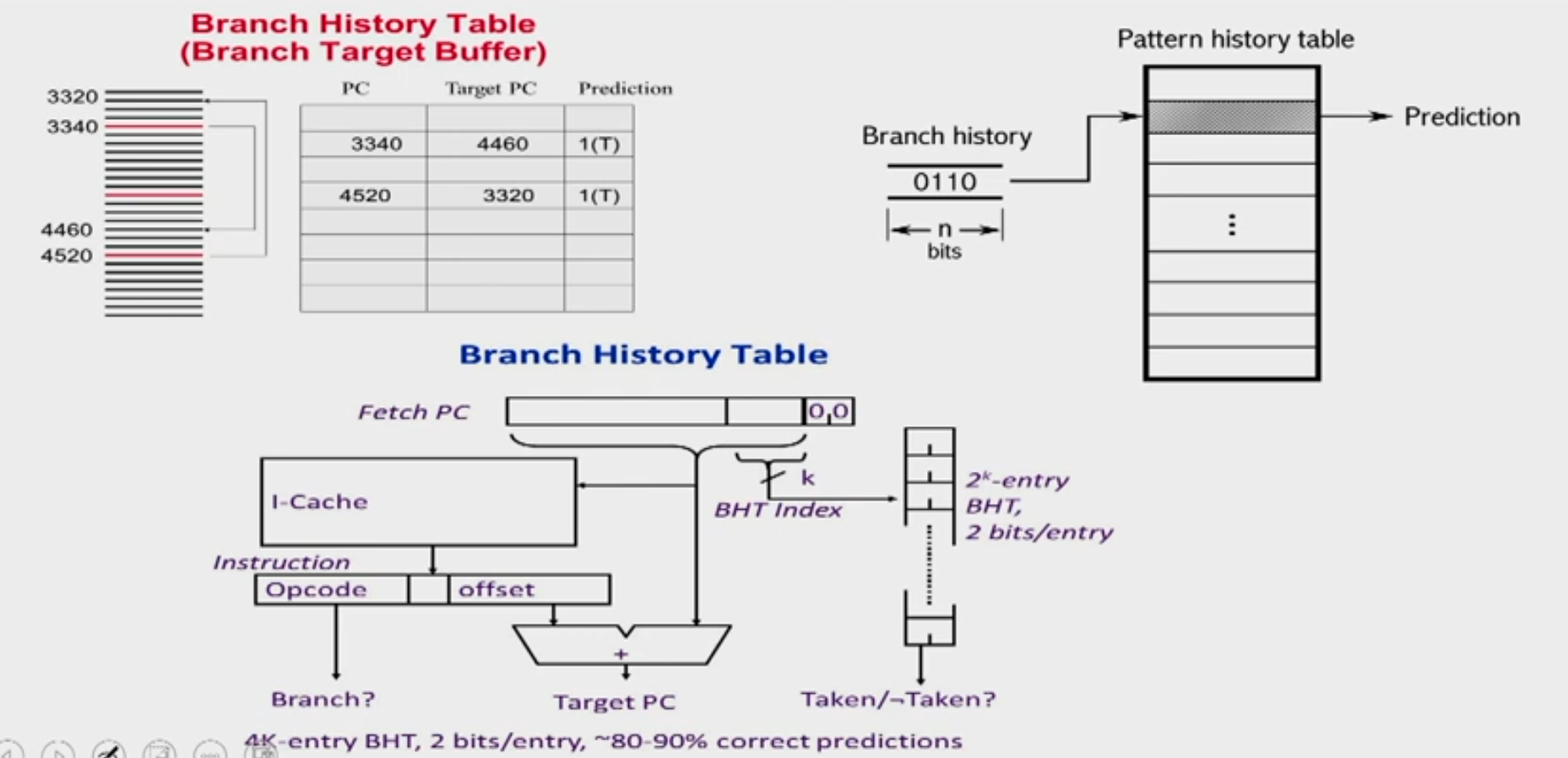
Use a Branch Prediction Buffer(BPB)
- Also called Branch Prediction Table (BPT), Branch History Table (BHT)
- Records previous outcomes of the branch instruction
- How to index into the table is an issue
-
A prediction using BPB is attempted when the branch instruction is fetched (IF stage or equivalent)
-
It is acted upon during ID stage (when we know we have a branch)
-
Has a prediction been made (Y/N)
- If not use default "Not Taken"
-
Is it correct or incorrect ?
-
Two cases:
- Case 1: Yes and the prediction was correct (known at ID stage) or No but the default was correct: No delay
- Case 2: Yes and the prediction was incorrect or No and the default was incorrect: Delay
Prediction Scheme with 1 or 2 bit FSM
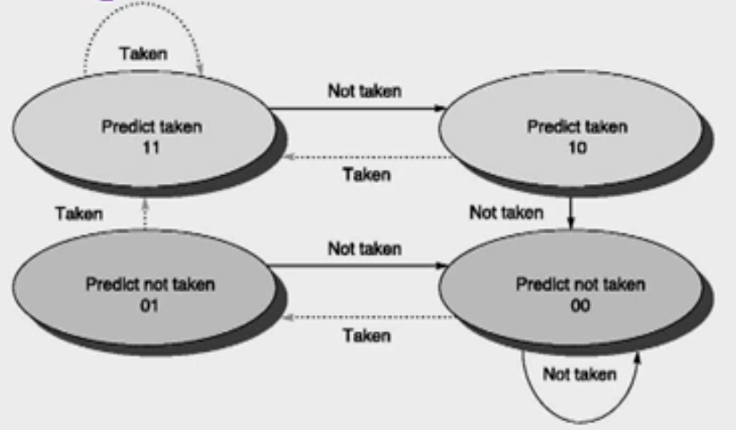
- The use of a 2-bit predictor will allow branches that favor taken (or not taken) to be mispredicted less often than the one-bit case. (reinforcement learning)
Branch Prediction In Hardware
- Branch prediction is extremely useful in loops.
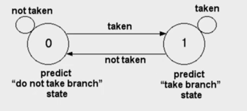
- A simple branch prediction can be implemented using a small amount of memory indexed by lower order bits of the address of the branch instruction. (branch prediction buffer)
- One bit stores whether the branch was taken or not
- The next time the branch instruction is fetched refer this bit
Advanced Branch Prediction Techniques
Basic 2-bit predictor:
- For each branch:- Predict T or NT
- If the prediction is wrong for two consecutive times, change prediction
Correlating predictor:
- Multiple 2-bit predictors for each branch
- One for each possible combination of outcomes of preceding n branches
if(x==2)  /*br-1*/
x=0;
if(y==2)  /*br-2*/
y=0;
if(x!=y)  /*br-3*/
    do this
else do that
Local predictor
- Multiple 2-bit predictors for each branch
- One for each possible combination of outcomes for the last n occurrences of this branch
Tournament predictor
- Combine correlating predictor with local predictor
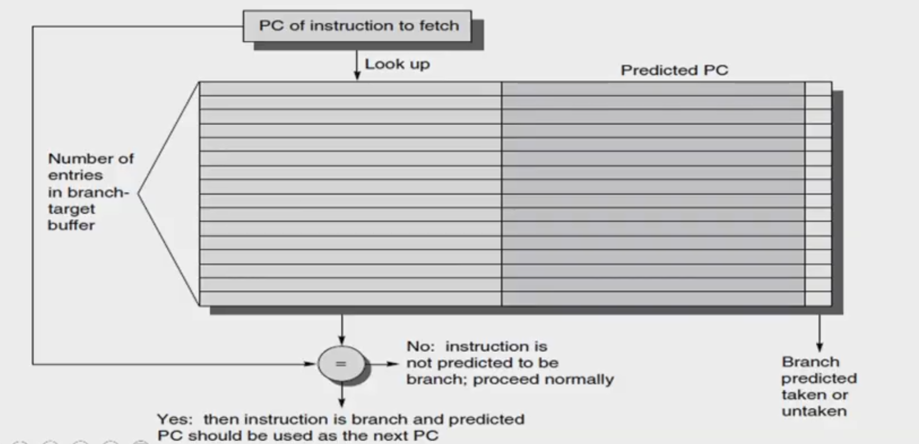
Branch-Target Buffer
- To reduce the branch penalty, know whether the as-yet-un-decoded instruction is a branch. If so, what the next program counter (PC) should be
- If the instruction is a branch and we know what the next PC should be, we can have a branch penalty of zero
- A branch-prediction cache that stores the predicted address for the next instruction after a branch is called a branch-target buffer (BTB) or branch-target cache.
Branch Folding
- Optimization on BTB to make zero cycle branch
- Larger branch-target buffer- store one or more target instructions
- Add target instruction into BTB to deal with longer decoding time required by larger buffer
- Branch folding can be used to obtain 0-cycle unconditional branches and sometimes 0-cycle conditional branches
Questions
Example 1
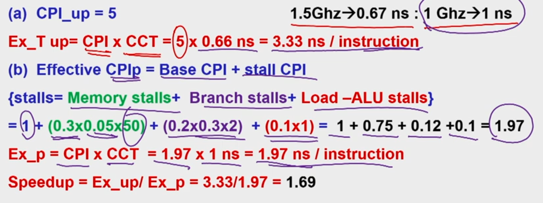
Given a non-pipelined architecture running at 1.5 GHz, that takes 5 cycles to finish an instruction. You want to make it pipelined with 5 stages. Due to hardware overhead the pipelined design will operate only at 1 GHz. 5% of memory instructions cause a stall of 50 cycles, 30% of branch instruction cause a stall of 2 cycles and load-ALU combinations cause a stall of 1 cycle. Assume that in a given program, there exist 20% of branch instructions and 30% of memory instructions. 10% of instructions are load-ALU combinations. What is the speedup of pipelined design over the non-pipelined design?
Ans:
Example 2
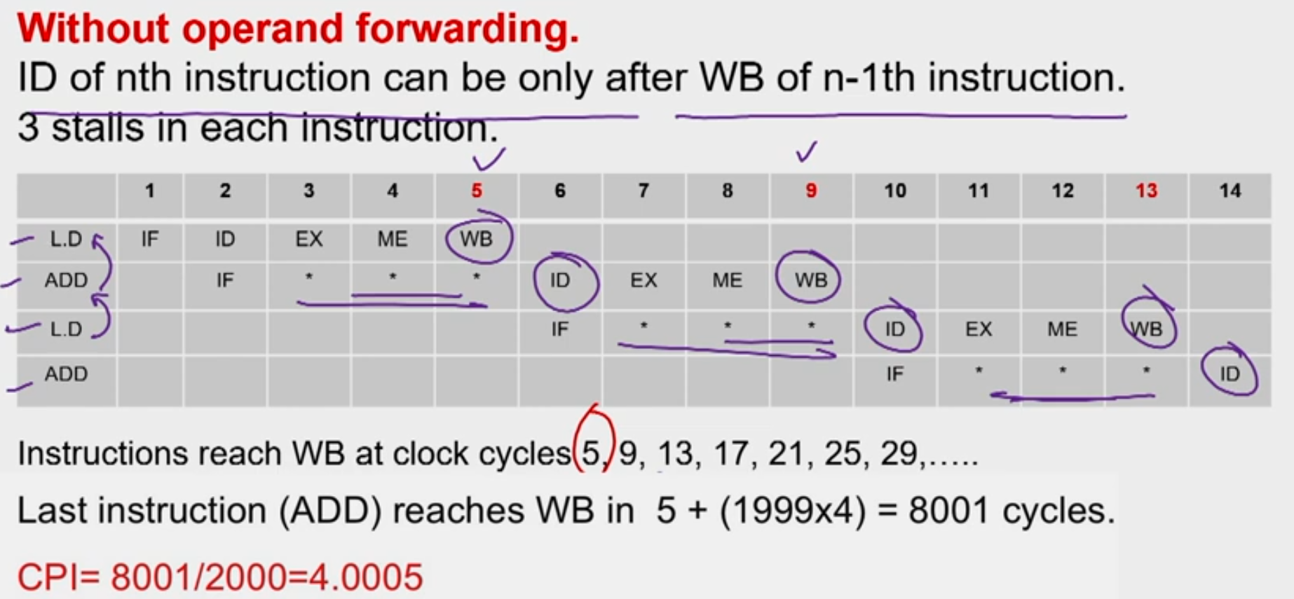
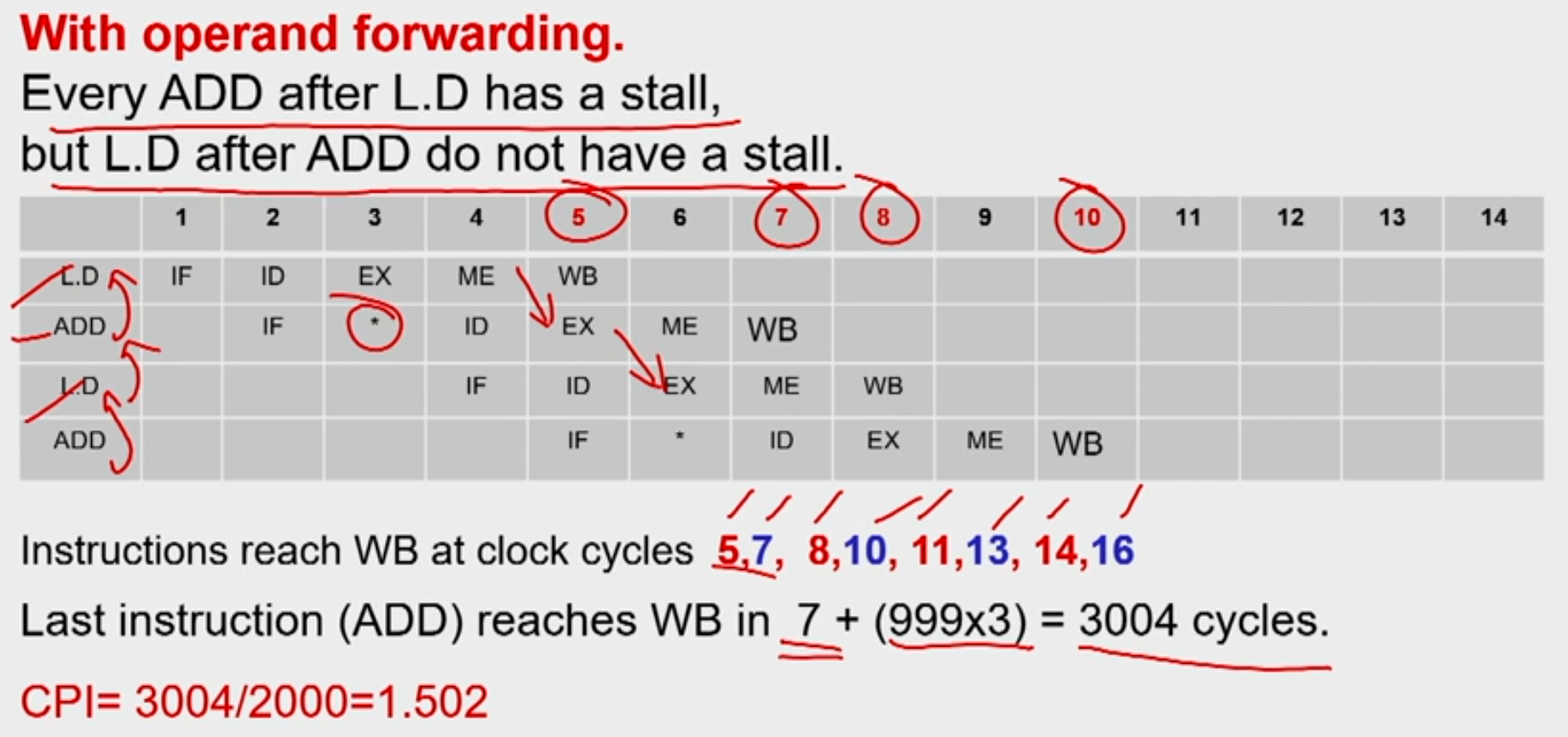
A program has 2000 instructions in the sequence L.D, ADD.D, L.D, ADD.D,..... L.D, ADD.D. The ADD.D instruction depends on the L.D instruction right before it. The L.D instruction depends on the ADD.D instruction right before it. If the program is executed on the 5-stage pipeline what would be the actual CPI with and without operand forwarding technique?
Ans:
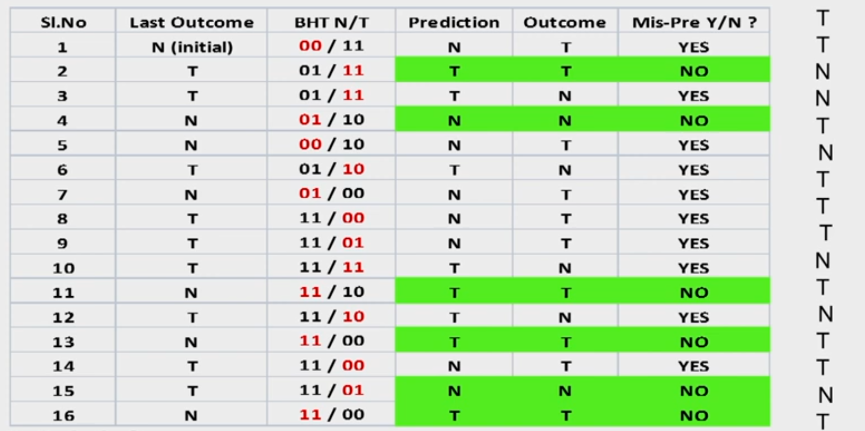
Example 3: Branch Prediction
Consider the last 16 actual outcomes of a single static branch. T means branch is taken and N means not taken.
{oldest> TTNNTNTTTNTNTTNT < latest}
A two level branch predictor of (1,2) type is used. Since there is only one branch in the program indexing to BHT with PC is irrelevant. Hence only last branch outcome only is used to index to the BHT. How many mis-predictions are there and which of the branches in this sequence would be mis-predicted? Fill up the table for 16 branch outcomes.
Ans:
Introduction
-
Pipelining overlaps execution of instructions Exploits Instruction Level Parallelism (ILP)
-
There are two main approaches:
- Compiler-based static approaches
- Hardware-based dynamic approaches
-
Exploiting ILP is to minimize CPI
- Pipeline CPI = Ideal (base) CPI + Structural stalls + Data hazard stalls + Control stalls
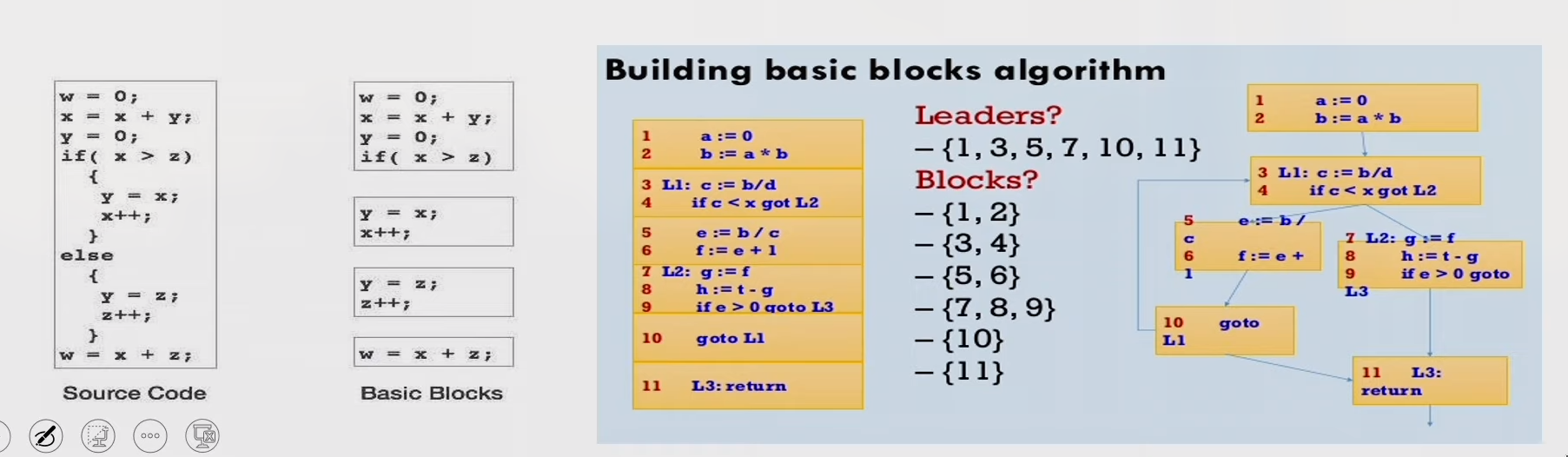
Parallelism limitation within Basic Block
- The basic block- a straight-line code sequence without branches in except to the entry and no branches out except at the exit.
- Parallelism with basic block is limited. Typical size of basic block few instructions only. Must optimize across multiple blocks (branches)
Data Dependence
- Loop-Level Parallelism
- Unroll loop statically or dynamically
- Challenges—> Data dependency
- Data dependence conveys possibility of a hazard
- Dependent instructions cannot be executed simultaneously
- Pipeline determines if dependence is detected and if it causes a stall or not
- Data dependence conveys upper bound on exploitable instruction level parallelism
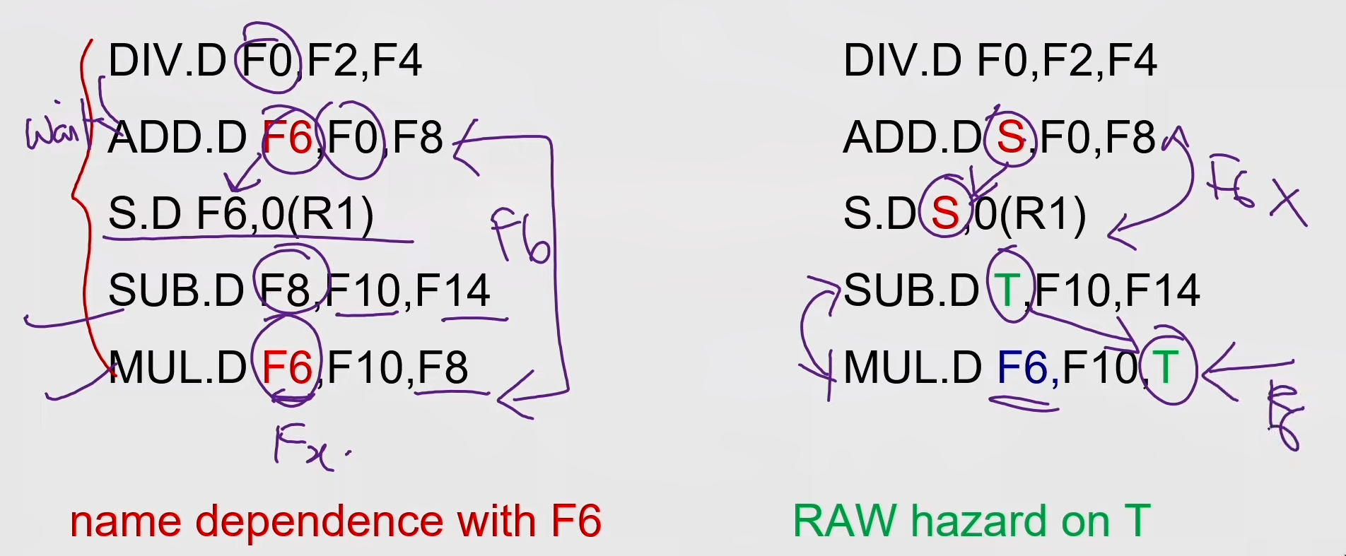
Name Dependence & Output dependence
- Two instructions use the same name but no flow of information.
- Not a true data dependence, but is a problem when reordering instructions
- Antidependence: instruction j writes a register or memory location that instruction i reads
- Initial ordering (i before j) must be preserved
- Output dependence: instruction i and instruction j write the same register or memory location
- Ordering must be preserved
- To solve, use register renaming techniques
Control Dependence
- Ordering of instruction with respect to a branch instruction
- Instruction that is control dependent on a branch cannot be moved before the branch so that its execution is no longer controller by the branch
- An instruction that is not control dependent on a branch cannot be moved
after the branch so that its execution is controlled by the branch.
if p1 {S1;};
if p2 {S2;};
- Instruction that is control dependent on a branch cannot be moved before the branch so that its execution is no longer controller by the branch
- An instruction that is not control dependent on a branch cannot be moved
after the branch so that its execution is controlled by the branch.
Compiler Techniques for Exposing ILP
- Find and overlap sequence of unrelated instruction
- Pipeline scheduling
- Separate dependent instruction from the source instruction by pipeline latency of the source instruction
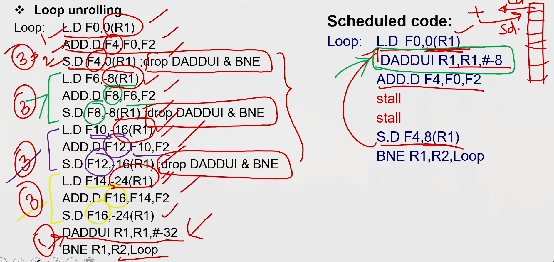
Example:
for (i=999; i>=0; i=i-1)
  x[i] = X[i] +s;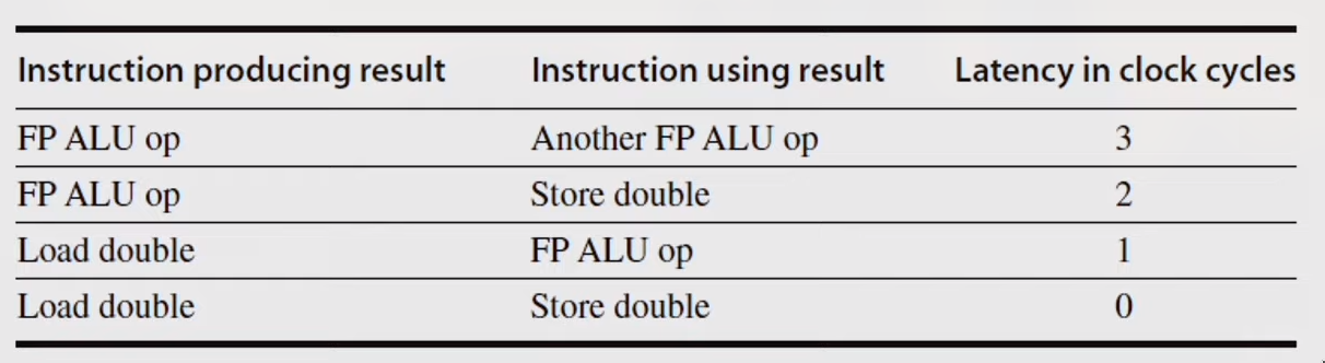
MIPS Assembly code for above code:
loop:
  L.D F0,0(R1)
  stall
  ADD.D F4,F0,F2
  stall
  stall
  S.D F4,0(R1)
  DADDUI R1,R1,#-8
  stall (assume integer load latency is 1)
  BNE R1,R2,Loop
Scheduled Code:
loop:
  L.D FO,0(R1)
  DADDUI R1,R1,#-8
  ADD.D F4,F0,F2
  stall
  stall
  S.D F4,8(R1)
  BNE R1.R2.Loop
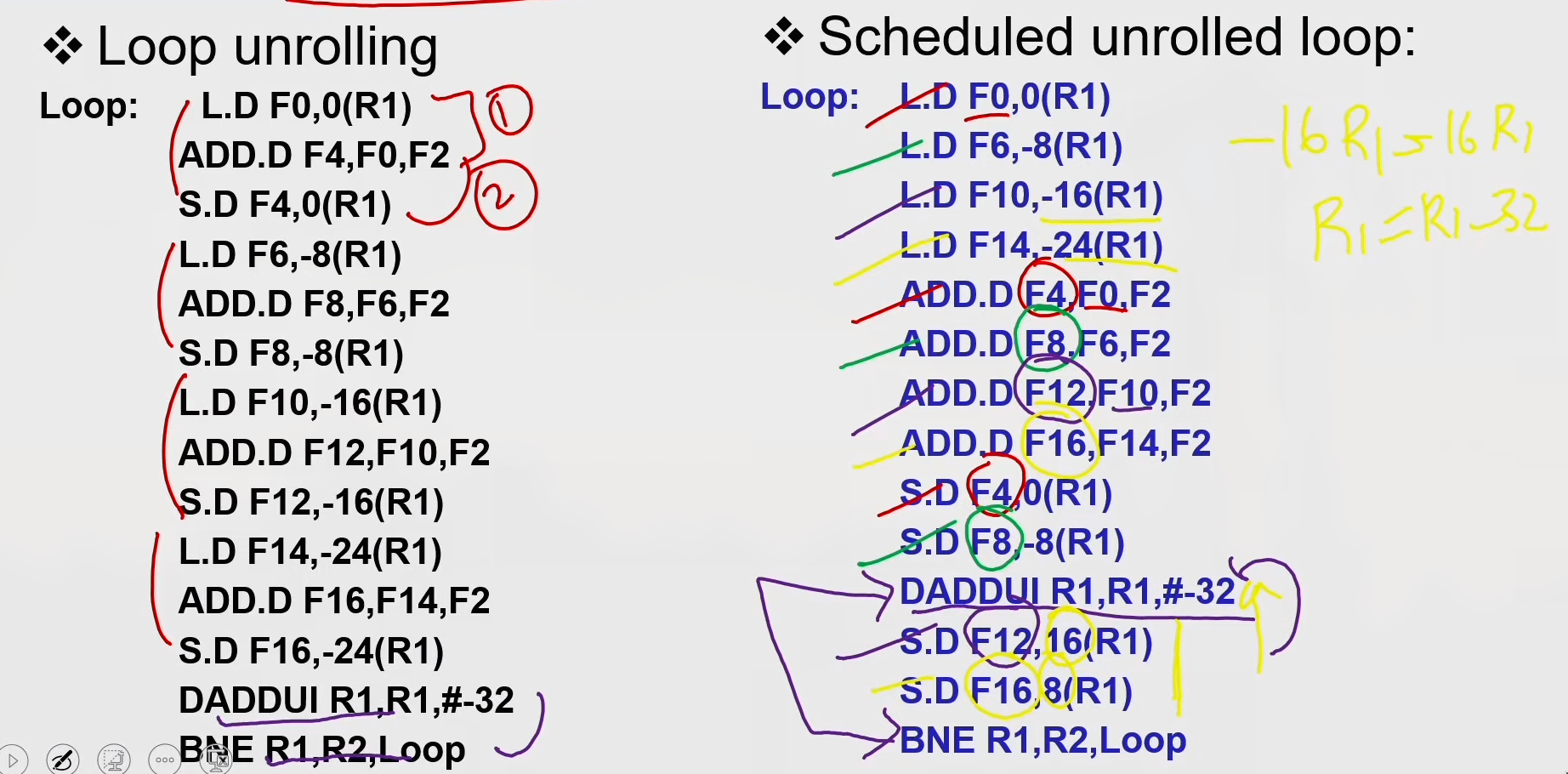
Loop Unrolling
Loop Unrolling / Pipeline Scheduling
Strip Mining
- Unknown number of loop iterations?
- Goal: make k copies of the loop body Number of iterations = n
- Generate pair of loops:
- First executes n mod k times
- Second executes n / k times
- Strip mining
- Example: Let n=35, k=4
- Loop 1 execute 3 times
- Loop 2 execute 8 times by unrolling 4 copies per iteration
Steps in Loop Unrolling and Scheduling
- Determine that unrolling the loop would be useful.
- Identify independency of loop iterations.
- Use different registers to avoid unnecessary constraints put in on same computations.
- Eliminate the extra test and branch instructions and adjust the loop termination and iteration code.
- Determine whether the loads and stores from different iterations are independent.
- Schedule the code, preserving any dependences needed to yield the same result as the original code.
Loop Unrolling & Pipeline Scheduling
- Limitations of loop unrolling:
- Code size limitations — I-cache miss
- Compiler limitations — register pressure
Dynamic Scheduling
- Rearrange execution order of instructions to reduce stalls while maintaining data flow.
- Advantages
- Compiler doesn't need to have knowledge of micro-architecture
- Handles cases where dependencies are unknown at compile time
str R2, 8(R1) ld R3, 16(R4) // will access same location if 8+[R1] == 16+[R4] - Disadvantages
- Substantial increase in hardware complexity
- Complicates exceptions
How dynamic scheduling works?
-
Limitation of simple pipelining.
- In-order instruction issue and execution.
- Instructions are issued in program order.
- If an instruction is stalled in the pipeline, no later instructions can proceed.
add rl,r2,r3 sub r4,rl,xr3 and r6,rl,r7 or r8,rl,r9 -
Limitation of simple pipelining.
- In-order instruction issue and execution.
- Instructions are issued in program order.
- If an instruction is stalled in the pipeline, no later instructions can proceed.
-
If instruction j depends on a long-running instruction i, currently in execution in the pipeline, then all instructions after j must be stalled until i is finished and j can execute.
DIV.D FO,F2,F4 ADD.D F10,FO,F8 SUB.D F12.F8,F14 -
Separate the issue process into two parts:
- checking for any structural hazards.
- waiting for the absence of a data hazard
-
Use in-order instruction issue but we want an instruction to begin execution as soon as its data operands are available.
-
out-of-order execution - out-of-order completion.
-
OOO execution introduces the possibility of WAR and WAW hazards
DIV.D FO,F2,F4      // can have divide by zero exception
ADD.D F6,FO0,F8
SUB.D F8,F10,F14    // already completed before div instruction
MUL.D F6,F10,F8
-
WAR and WAW hazards — solved by register renaming
-
Possibility of imprecise exception (2 possibilities).
- The pipeline may have already completed instructions that are later in program order than the instruction causing the exception.
- The pipeline may have not yet completed some instructions that are earlier in program order than the instruction causing the exception
-
To allow out-of-order execution, split the ID stage into two
- Issue-Decode instructions, check for structural hazards.
- Read operands-Wait until no data hazards, then read operands.
-
In a dynamically scheduled pipeline, all instructions pass through the issue stage in order (in-order issue); however, they can be stalled or bypass each other in the second stage (read operands) and thus enter execution out of order.
-
Done by - score boarding technique
-
Approach used - Tomasulo’s algorithm
Register Renaming
- Register renaming is done by reservation stations (RS)
- Each RS Contains:
- The instruction (operation to be done)
- Buffered operand values (when available)
- Reservation station number of instruction providing the operand values
- RS fetches and buffers an operand as soon as it becomes available (not necessarily involving register file)
- Pending instructions designate the RS that will provide input
- Result values broadcast on common data bus (CDB)
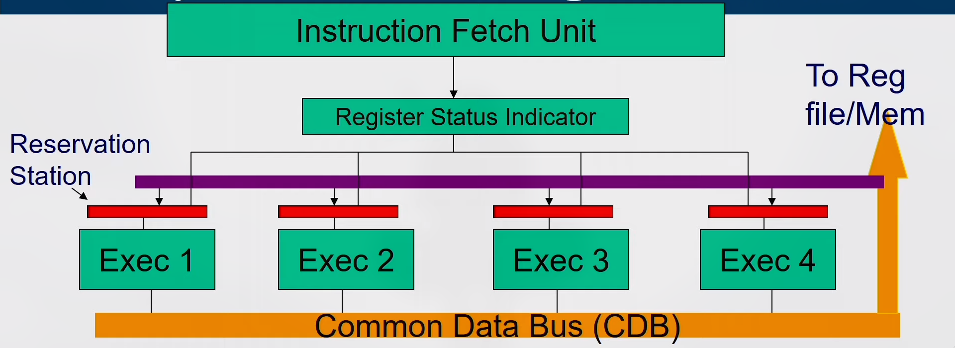
Tomasulo's Algorithm
- Load and store buffers contain data and addresses.
- They also act as RS
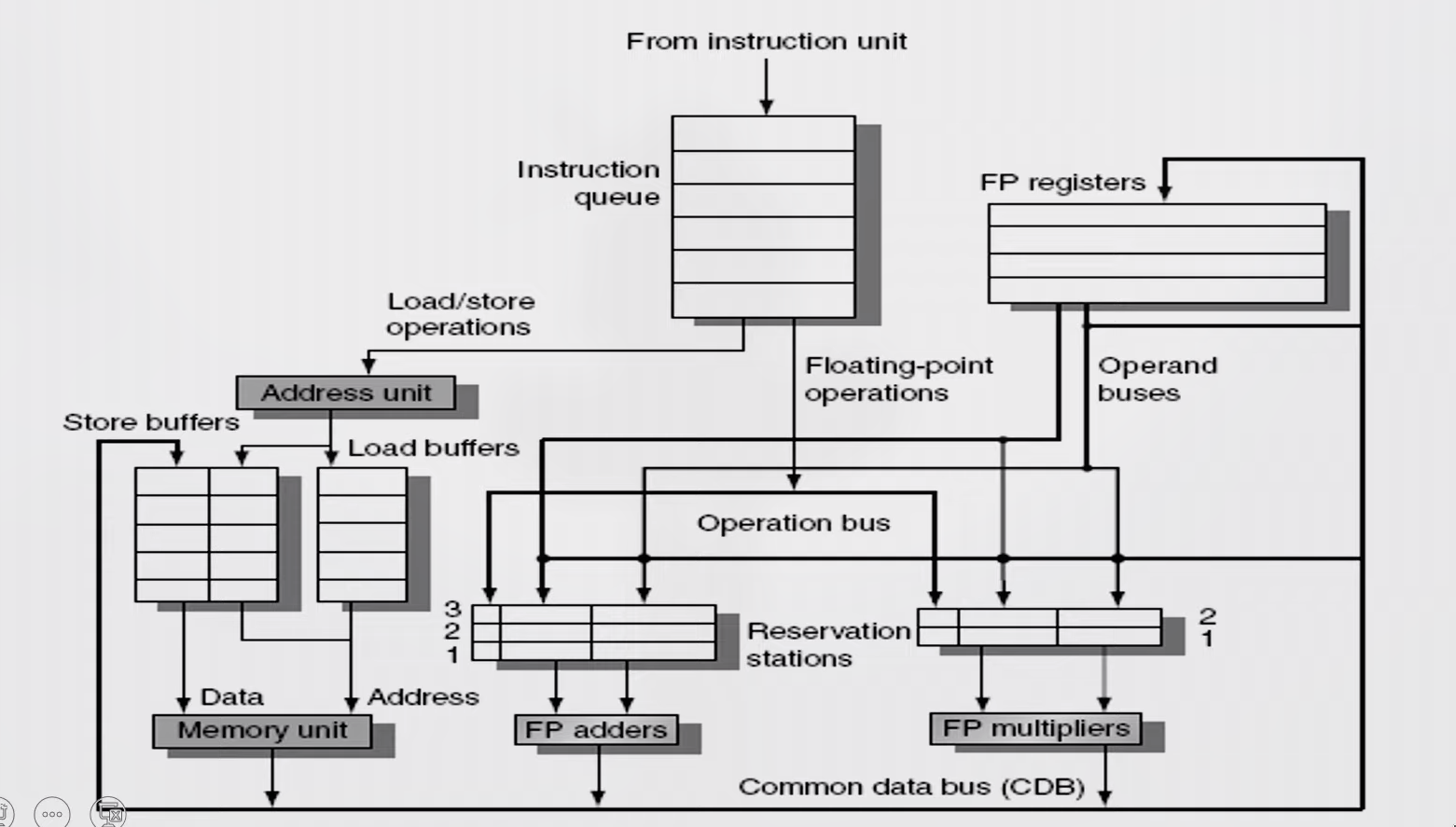
Issue
- Get next instruction from FIFO queue
- If RS available, issue the instruction to the RS with operand values if available
- If operand values not available, stall the instruction
Execute
- When operand becomes available, store it in any reservation stations waiting for it
- When all operands are ready, execute the instruction
- Loads and store uses buffers
- No instruction will initiate execution until all branches that precede it in program order have completed
Write result
-
Write result into CDB (there by it reaches the reservation station, store buffer and registers file) with name of execution unit that generated the result.
-
Stores must wait until address and value are received
-
Instructions are fetched one by one and decoded to find the type of operation and the source of operands
-
Register Status Indicator indicates whether the latest value of the register is in the reg file or currently being computed by some execution unit and if so, it states the execution unit number
-
If all operands available then operation proceeds in the allotted execution unit, else, it waits in the reservation station of the allotted execution unit pinging the CDB
-
Every Execution unit writes the result along with the unit number on to the CDB which is forwarded to all reservation stations, Reg-file and Memory
Reservation Station
-
Each reservation station has seven fields.
-
{Op, Qj, Qk, Vj, Vk, A, Busy}
-
- Op -The operation to perform on source operands S1 and S2.
-
2,3. Qj, Qk -The reservation stations that will produce the corresponding source operand; a value of zero indicates that the source operand is already available in Vj or VK.
-
4,5. Vj, Vk —The value of the source operands. Only one of the V field or the Q field is valid for each operand. For loads, the VK field is used to hold the offset field.
-
- A -Used to hold information for the memory address calculation for a load or store. Initially, the immediate field of the instruction is stored here; after the address calculation, the effective address is stored here.
-
- Busy -Indicates that this reservation station and its accompanying functional unit are occupied.
Reservation Station Indicator
- The register file has a field, Qi: (RSI)
- Qi-The number of the reservation station that contains the operation whose result should be stored into this register.
- If the value of Qi = 0 no currently active instruction is computing a result destined for this register, meaning that the value is simply the register contents.
Digital Electronics
Introduction
- TTL
- CMOS Logic
- Basic Gates
- Boolean Algebra
- Karnugh Map
- Tabular Method
- Static and Dynamic Hazards
Combinational Circuits
-
Adders - half, full, look-ahead carry
-
2's Complement, BCD Adders
-
Parity Generator/Checker
-
Magnitude Comperator
-
ALU
-
Unweighted Code
-
Error Detection and Correction
-
Decoder
-
Encoder
-
Multiplexer
-
Demultiplexer
Flip Flops
- Latch - SR, Gated, D
- Flip-Flops - Edge triggered, SR, D, JK, T
- Async Inputs
- Master-Slave Flip-Flops
- Conversion of Flip-Flops
- Applications of Latch and Flip-Flops
- Monostable Multivibrator
- Astable Multivibrator
- Crystal-controlled Clock Generator
Shift Registers
- Register, Shift Register
- Async Counter
- Sync Counter
Sequential Machines
- FSM
- Mealy, Moore
- Synthesis of synchronous sequential circuits
Extras
- D2A and A2D Converters
- Memory
- DRAM
- SRAM
- ROM
Multiplexers
- It is a combinational circuit which have many data inputs and single output depending on control or select inputs
- For N input lines, log n (base2) selection lines, or we can say that for 2^n input lines, n selection lines are required
- Logic like if, else if, else statements
- 2x1 Mux
Y = S0'*D0 + S0*D1
| S0 | Y |
|---|---|
| 0 | D0 |
| 1 | D1 |
- 4x1 Mux
Y = S1'*S0'*D0 + S1'*S0*D1 + S1*S0'*D2 + S1*S0*D3
| S1 | S0 | Y |
|---|---|---|
| 0 | 0 | D0 |
| 0 | 1 | D1 |
| 1 | 0 | D2 |
| 1 | 1 | D3 |
Demultiplexers
Decoder
Encoder
Parity Generator/Checker
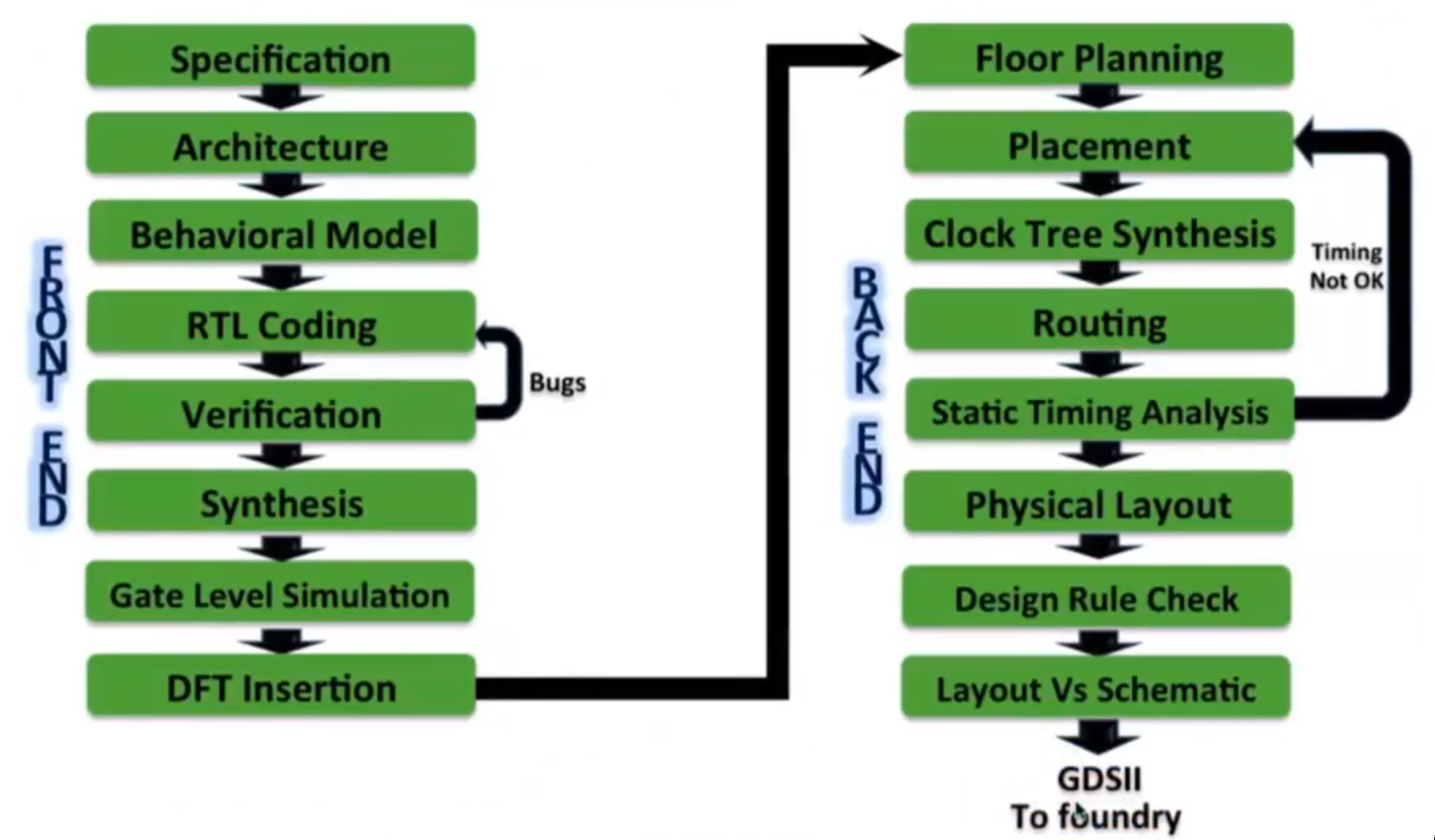
ASIC Design Flow
Verilog HDL
- Hardware Description Language
- IEEE standard 1364-2001 - describes syntax, not the style
- Synthesizable Constructs & Constructs for Simulation also.
- Synthesis: converting rtl code into netlist
- Digital and Analog(only simulation) design language
Abstraction Level
-
Circuit Level
- CMOS Circuit
-
Gate Level
- Basic gates are available as "Primitives"
-
Data Flow Level
- Register Transfer Level
- Realized through concurrent assignments
-
Behavioural Level
- Highest level of design description
- Function only
- Stimulus generation
- No architecture
- Design modelling
Verilog Data Types
Data Types
Values and Strength
-
Values
- 0 : represents a logic zero, or a false condition
- 1 : represents a logic one, or a true condition
- x : represents an unknown logic value
- z : represents a high-impedance state
-
Strength
- Strongest signal prevails
- Useful for switch level modelling and not for RTL
- When two signals with opposite value and same strength combine, the resulting value is x
By default every variable will have 'x' value. In case of tristate buffer it will have high impedance 'z'.
Strength levels are used in switch level modeling using cmos for building the circuit and not used for rtl.
Numbers
<size>'<base><number>
-
size = number of bits
-
base = binary(b), octal(o), decimal(d), hexadecimal(h)
-
number = 0-9, a-f, x, z
-
For example:
4'b0010 -
12'o43xzwill be expanded like:
  4    3    x    z
 100  011  xxx  zzz
-
Underscores improve readability eg.
32’h a_bc_2is the same as32’b 1010_1011_1100_0010 -
Zero, X and Z extension
4'b1is the same as4'b 00014'bx1is the sameas4'b xxx14'bz1s the same as4'b zzzl
-
Unsized numbers will have by default 32 bit
'h4ais the same as32'b 0000_0000_0100_1010
NET and REG
Data types in Verilog are divided into NETS and Registers.
Nets - (net Data Type)
The nets variables represent the physical connection between structural entities. These variables do not store values (except trireg); have the value of their drivers which changes continuously by the driving circuit. Some net data types are wire, tri, wor, trior, wand, triand, tri0, tri1, supply0, supply1 and trireg. wire is the most frequently used type. A net data type must be used when a signal is:
- driven by the output of some device
- declared as an input or in-out port
- on the left-hand side of a continuous assignment
Declaration and Assignment:
wire A, B, C
assign C = A & B
By default all the ports are wire datatype
- Nets are continuously driven by combinational logic
Regs - (reg Data Type)
The register variables are used in procedural blocks which store values from one assignment to the next. An assignment statement in a procedure acts as a trigger that changes the value of the data storage element. Some register data types are: reg, integer, time and real.
Reg is used for describing logic, integer for loop variables and calculations, real in system modules, and time and realtime for storing simulation times in test benches.
- Using reg does not means we will get physical hardware Registers. It depends on coding style not on the datatype.
- Assignments — Registers and nets can be mixed
Port Assignments
- Input, Output and Inout - by default are wire datatype
Integers Data Type
- Integers store values as signed quantities
- Mostly synthesizable
- Arithmetic operations performed on integer variables produces 2's compliment result
- Procedural assignments shall be used to trigger value changes in integers
Real Data Type
-
Allows decimal and scientific notation
-
Example:
0.210, 3.1415, 4.6e-2, -2.5 -
Not synthesizable
-
Declaration and Assignment:
real real_num;
integer int_num;

real_num = 67.9
int_num = real_num;   <-- will roundoff to 68
Time Data Type
-
For storing and manipulating simulation time quantities
-
Not synthesizable, useful for testbench implementation
-
Declaration and Assignment:
time sim_time; sim_time = $time; <-- current simulation time will be assigned to variable sim_time -
The time variables behave same as a reg of at least 64 bits, with the least significant bit being bit 0
-
The time variables are unsigned quantities, and unsigned arithmetic is performed on them
Vectors
- Represent Buses
- Slices - range direction must be same as vector
For example:
reg [3:0] z_bus;wherez_bus[3]=MSB andz_bus[0]=LSB
Scalar Array is an array of one 1-bit data type. Ex – reg a[3:0] - This is an array of size 4 and where each element can hold 1-bit data. Vector Array is an array of vectors. As we have seen earlier vectors are nothing but a group of 1-bit data types combined to increase the size of data type. Ex – reg [3:0] a [7:0] - This is an array of size 8, where each element can hold 4-bit reg data.
Arrays
-
Arrays for variables types (reg, integer, time,real,realtime) are possible.
-
Net Arrays:
  reg my_reg [0:5];        // Declares an array of 6, 1 bit registers
  my_reg[2] = 1'b1;        //Assigns value 1 to the 3rd element of array

  reg arrayb [7:0] [0:255]; // Declares a two dimensional array of
                            // one bit registers
  arrayb[1][0] = 0;         // Assigns 0 to the bit referenced by indices [1] [0]

  wire w_array [7:0] [5:0]; // Declares a two dimensional array of wires

  integer inta[1:64];       // Declares an array of 64 integer values
  reg [1:n] rega;    //n bit register (vector)

  reg rega [1:n];    //array of n, 1 bit registers
- Horizontal = vector, Vertical = array
Memory
- A one dimensional array with elements of type reg
- Used to model ROMs, RAM, and reg files
  reg [7:0] mema [0:255]; // declares a memory mema of 256 8-bit
                          // registers. The indices are 0 to 255
  mema[1] = 0
- An n-bit reg can be assigned a value in a single assignment, but a complete memory cannot.
- Use for loop to initialize the whole memory
Parameters
- Parameters are not variables, they are constants
module ram (clk,rst,din,radd,wadd,dout);

  parameter dt_width = 8; // Defines dt width as a constant value 8
  parameter ad_depth = 256; // Defines ad depth as a constant value 256

  ...
  reg [(dt_width - 1) : 0] mem [(ad_depth - 1) : 0];
    // Declaring a 256X8 memory using parameters
  ...

endmodule
- The parameter override values have to be contiguous, that is any parameter cannot be skipped during override
- Overriding a module's parameter values during initialization
module ram (clk,rst,din, radd wadd,dout) ;
  parameter dt_width = 8;
  parameter ad_depth = 256;
  ...
  reg [(dt_width - 1):0] mem [(ad_depth-1):0];
  ...
endmodule

//Assignment by ordered list

module system(...);
  input  rst,clk;
  output dout, done;

  //Overriding dt_width only
    ram #( 16 ) MEM1 (.clk(clk),.rst(rst),...);

  //Overriding both dt_width and ad_depth
    ram #( 16, 512) MEM2 (.clk(clk),.rst(rst),...):

endmodule

// Assignment by name

module system(...);
  input rstrclks 5
  output dout, done;

  //Overriding dt_width only
  ram #( .dt_width(16) ) MEM1 (.clk(clk),.rst(rst),...):

  //Overriding ad_depth only
  ram #( .ad_depth(512) ) MEM2 (.clk(clk),.rst(rst),...):

  //Overriding both dt_width and ad_depth
  ram #(.dt_width(16), .ad_depth(1024) ) MEM3 (.clk(clk),...):

endmodule
String
- A string is a sequence of characters enclosed by double quotes ("") and contained on a single line
- 8-bit ASCII value represents one character
reg [8*12:1] string_reg;
  // 13 characters requires a 8*12, or 96 bits wide reg
string_reg="Some text...";
Operators
Logical Operators
- AND &&, OR ||, NOT !
- Evaluates to a single bit value (1-True, 0-False, X-Unknown)
- Any non-zero value means True
- Operation with Unknown(X) will result in Unknown(X)
Bitwise Operators
- AND (&)
- OR (|)
- XOR (^)
- NEGATION (~)
- XNOR (~^ or ^~)
Relational Operators
- AND (&)
- OR (|)
- XOR (^)
- NAND (~&)
- XNOR (~^ or ^~)
- NOR (~|)
Shift Operators
-
Shift Right (>>)
-
Shift Left (<<)
-
and << are Logical Shift Operators
-
and <<< are Arithmetic Shift Operators
-
Result in same length as operand
a=5'b10100;
b=a<<<2;    //b == 5'b10000
c=a>>>2;    //c==5'b11101 ,vacated bit is filled with MSB if the left operand is signed
d=a<<2;    //d==5'b10000
e=a>>2;    //e==5'b00101
Concatenation Operators
-
It is the joining together of bits resulting from two or more expressions within
{ } -
The concatenation operators are used to form a bit pattern by joining two or more expressions
-
Operands must be sized
reg a;
req [2:0]b, c;
reg [7:0]x, y, z;

a = 1'b1; b = 3'b100; c = 3'b110;

x = {a, b, c};            // x =01100110
y = {b, 2'b01, a};        // y =00100011
z = {x[1:0], b[2:1], c};  // z =01010110

x = {{2{a}}, b, {2{c}}};  // x =11100110110
Relational Operators
-
, >=, <, <=
- Evaluates to a single bit value 0 (False) or 1 (True)
- Operation with Unknown(X) will result in Unknown(X)
Equality
- Logical: ==, !=
- Case: ===, !== (not synthesizeable)
a=4'b1x0z; b = 4'b1x0z;

a == b // Evaluates to x
a != b // Evaluates to x
a === b // Evaluates to 1
a !== b // Evaluates to 0
Conditional Operators
- conditional_expression ? true_expression : false_expression;
Arithmetic Operators
-
Multiplication [*]
-
Add [+]
-
Subtract [-]
-
Division [/]
-
Modulus [%]
-
Expensive on gates
-
Represent physical hardwares eg.
addwill represent adders gates
Points to be noted
integer i;
reg [15:0] a,z;

a = -4'd12;
z = a/3;        //evaluates to 21841
i = -12/3;      // i evaluates to -4
i = - 'd12/3;   // i evalautes to
                // (2^32 - 12)/3 = 1431655761

a = -12/3       // a evaluates to 65532
                // 65532 = 2's complement of -4
- Negative register values are stored as 2’s complement, but are treated by arithmetic operators as unsigned operands
- if no base specifier is used
References
- https://www.theoctetinstitute.com/content/verilog/arrays/
Compiler Directives and System Tasks
Internal variable monitoring system tasks
-
$display, $write, $strobe, $monitor
-
$display or $write displays the specified variables once when the command is executed in the code flow
-
$display automatically adds a newline character to the end of its output, whereas the $write task does not
// syntax
$display("mreg = %h hex, %d decimal", mreg, mreg);
- $strobe display simulation data at a selected time (at the end of the current simulation time), when all the simulation events that have occurred for that simulation time
- Each time a variable or an expression in the argument list changes value, the entire argument list is displayed at the end of the time step.
Simulation Time related Tasks
- $time - Returns an unsigned integer that is a 64-bit time, scaled to the timescale unit of the module that invoked it
File input and output system tasks
-
$fopen, $fclose, $readmemb
-
The function $fopen opens the file specified as the filename argument and returns either a 32 bit multichannel descriptor, or a 32 bit file descriptor.
-
The channel descriptor for each channel is a 32 bit value with only one bit set that corresponds to the channel number
-
$fmonitor used to write within the file
-
$stop causes simulation to be suspended
-
$finish makes the simulator exit and pass control back to the host operating system
-
$finish(2) will print the CPU usage time
Probabilistic distribution function system text
$random
- The function returns a new 32-bit random signed integer number each time it is called
- Seed parameter controls the numbers that $random returns
reg [23:0] rand, seed num;
rand = Srandom (seed num);
Compiler directives
- `include, `define , `timescale
`define
- Creates a macro for text substitution
- Can be used both inside and outside module definitions
- Can be used in the source description by using the ( ` ) character, followed by the macro name
`define dt_width 8
`define ad_depth 256
`include
- Used to insert the entire contents of a source file in another file during compilation
- Used to include global or commonly used definitions and tasks
//File - state_definition.v

`define HOLD 0
`define RESET 1
`define SET 2
`define TOGGLE 3

//Main file

`include "state_definition.v"
`timescale
- Specifies the time unit and time precision of the modules that follow `timescale
- time_unit specifies the unit of measurement for times and delay
- time_precision specifies how delay values are rounded before being used in simulation
- time_unit > time_precision
- Error if some modules have a `timescale specified and others do not
`timescale time_unit / time_precision
`timescale 10ns / 10ps
Verilog - Assignments
Types of assignments
Continuous assignments
- Assigns values to nets
- This assignment occurs whenever the value of the right-hand side changes
- Executes in parallel
- Continuously active
- Order independent
- LHS must be wire data type, RHS could be reg or wire
wire c, a, b;
assign #2 c = a & b;
- Here, RHS will be computed after 2 time unit delay, then result will be assigned to LHS
Procedural assignments
- Update the value of variables under the control of the procedural flow constructs that surround them
- Each procedure represents a separate activity flow in Verilog, all of which run in parallel
- For multiple parallel procedural blocks order of execution is indeterministic.
- LHS must be reg datatype
initial Block
- Execution starts at zero simulation time
- Once executable only
- Only for testbench not for rtl
always Block
- Repeats continuously throughout the duration of the simulation
- If an always construct has no control for simulation time to advance, it will create a simulation deadlock condition
Event Controls
- Event - a change in value on a register or net.
- A posedge is detected on the transition from 0 to x, z, or 1, and from x or z to 1
- A negedge is detected on the transition from 1 to x, z, or 0, and from x or z to 0
always @ (triggering_signal)
  begin
    ......
  end
Sensitivity List
- Without sensitivity list ,the always block will loop continuously without waiting for a triggering event.
- All net and variable identifiers which appear in the statement will be automatically added to the event expression
  module ev_exp_check (a, b, c, d, f, y);
  input [1:0] a, b, c, d, f;
  output y;
  reg [1:0] y;

  // equivalent to @(a or b or c or d or f)
  always @(*)
    y = (a & b) | (c & d) | f;
  endmodule
Level-sensitive event control
wait_statement
-
It is a special form of event control. The nature of the wait statement is level-sensitive
-
wait statement evaluates a condition, and, if it is false, the procedural statements following the wait statement remains blocked until that condition becomes true
-
Only for testbench
begin
  wait (!enable)
  #10 a = b;
  #10 c = d;
end
Procedural Assignment Delays
Regular Delay
- When the delay is specified on the LHS of the procedural assignment, it means that this is the delay before the RHS is evaluated and assigned to the LHS.
#5 b = 1'b1;
Intra-assignment Delay
- The RHS of the equation is evaluated at the current time but the assignment is not made until after the delay time
- intra-assignment delay can be applied to both blocking assignments and non blocking assignments
a = #10 b;
Block statements
-
The block statements are a means of grouping two or more statements together so that they act syntactically like a single statement.
-
Two Types :
- Sequential block, also called begin-end block
- Parallel block, also called fork-join block
-
Both sequential and parallel blocks can be named by adding : name_of_block after the keywords begin or fork.
Sequential Block (begin - end block)
- Statements executes in sequence, one after another
- Delay values for each statement is treated relative to the simulation time of the execution of the previous statement
- Control is passed out of the block after the last statement executes
- Final delay will be addition of all delays
initial
  begin
    .....
  end
Parallel Block (fork - join block)
- Statements executes concurrently
- Delay values for each statement is considered relative to the simulation time of entering the block
- Delay control can be used to provide time-ordering for assignments
- Control is passed out of the block when the last time-ordered statement executes
- Final delay will be maximum of all delays
initial
  fork
    .....
  join
Event timing controls
- Not for synthesis
@(posedge clock) a = b;- event control with regular delaya = @(posedge clock) b;- event control with intra-assignment delay
Procedural Block
Type_of_block @ (sensitivity_list)
  begin : name_of_block
    local variable declarations;
    procedural assignment statements;
  end
Blocking Assignments
- Blocking Assignment are represented with the sign "="
- These are executed sequentially, i.e. one statement is executed then the next statement is executed.
- One statement blocks the execution of other statements until it is executed.
- Any delay attached is also got added to delay in execution of next statements.
Non-blocking Assignments
- A non-blocking assignment is represented with the sign "<="
- Its execution is concurrent with that of the following assignment or activity
- For all the non-blocking assignments in a block, the right-hand sides are evaluated first. Subsequently the specified assignments are scheduled
- It is illegal to use a non-blocking assignment in a continuous assignment statement or in a net declaration
- The order of the execution of distinct non blocking assignments to a given variable shall be preserved.
- Usually increases hardware
Example Images and Code
Coding Guidelines
-
It is best to use blocking assignments when describing combinational circuits, so as to avoid accidentally creating a sequential circuit.
-
Use Non-blocking assignments when describing sequential circuits.
-
Do not mix blocking and non blocking assignments in the same always block
-
When combining combinational and sequential code into a single always block, code the always block as a sequential always block with non blocking assignments.
if else Statement
if (condition)
  begin // Alternative 1
    assignment1;
  end
else if (condition 2)
  begin // Alternative 2
    assignment2;
  end
else
  begin // Alternative 3
    assignment3;
  end
Case Statements
- Multiway decision statement that tests whether an expression matches one of a number of other expressions and branches accordingly
case (expression)
  case_item_1 : statement 1;
  case_item_2, case_item_3  : statement_2;
  case_item_4 : statement 3;
  .....
  default : default_statement;
endcase
Loop Statements
for loop
- Its execution is a three-step process, as follows:
a. Initialize a variable that controls the number of loops executed.
b. Evaluates an expression if the result is zero, the loop exits, and if it is not zero, the for-loop executes its associated statement(s) and then perform step c.
c. Executes an assignment, normally modifies the value of the loop-control variable, then repeats step b.
for (i=0; i<10; i=i+1)
  begin
  ...
  end
while loop
-
Executes a statement until the expression becomes false.
-
If the expression starts out false, the statement does not execute at all.
-
Not synthesizable
while(condition)
  begin
  ...
  end
repeat, forever loops
-
Repeat executes a statement, fixed number of times.
-
If the expression evaluates to unknown or high impedance, it is treated as zero, and no statement is executed.
-
Forever continuously executes a statement
-
Not synthesizable
Functions
- Functions can enable other functions but not another task
- Functions always execute in zero simulation time
- Functions must not include delay, timing or timing control statements
- Functions must have at least one input argument
- Functions return a single value. They cannot have output or inout arguments
function [width] function_name (input input_args);
  begin
    //function_body;
  end
endfunction


// Example parity_cal
reg [31:0] address;

function parity cal;          //function declaration
  input [31:0] data;
  begin
    parity_cal = ~ ^ data;
  end
endfunction

always@ (address)
  parity reg = parity_cal(address);   //function call
Tasks
- Tasks can enable other tasks and functions
- Tasks may execute in non-zero simulation time
- Tasks may include delay, timing or timing control statements
- Tasks may have zero or more arguments of type input, output or inout
- Tasks do not return a value but can pass multiple values through output and inout arguments
task task_name (input/inout/output args);
  begin
    //task_body;
  end
endtask


// Example parity_cal
reg [31:0] address;
reg parity_reg;

task parity cal;          //task declaration
  input [31:0] data;
  output parity;
  begin
    #1 parity_cal = ~ ^ data;
  end
endtask

always@ (address)
  parity reg = parity_cal(address, parity_reg);   //task call
FSM
Basic FSM structure
Moore Vs Mealy
Common FSM coding styles Registered outputs
Specifying Registers in verilog
- initial block in not synthesizable
- posedge will result in flip flop
- use non-blocking for sequential
-
only use reg within procedural block
-
if the logic is sequential then only the clock will be in sensitivity list
-
because the logic is synchronous everything will be in control of clock- clock is edge sensitive and reset is level sensitive
-
hardware depends on coding style not the data type
-
Asynchronous reset =
posedge clock or posedge reset -
Synchronous reset =
posedge clock
- use default assignment for avoiding unwanted latches
- Always use default case statement
- Assign every output in every branch
- Use default assignments
Synthesis of Operators
- Nearly all of the Verilog operators are Synthesizable, however there are a few issues to bear in mind when using them.
- Some synthesis tools can choose macro-cells automatically
- Some synthesis tools will allow you to specify what architecture should be used
Resource Sharing
- Some synthesis tools can perform this optimization automatically
- If the synthesis tool cannot perform this optimization, the Verilog code can be re-written to achieve the same result
- Use parentheses to optimize logic structure
- if else if - infers priority encoded "cascading" mux’s in your design
- Case — infers "tall and skinny" mux’s in your design with no priority
Interview Questions
C++ Interview Questions
- What is the value of 'x' ?
int x=10;
sizeof(x++);
cout<<x;
Ans: 10, because sizeof() computes at compile time, so x++ never executes
- auto, static, register, mutable, extern initialize with 0 (global scope variables are also initialized with 0)
- Type Conversion:
bool -> char -> short int -> int -> unsigned int -> long -> unsigned long -> long long -> float -> double -> long double
1    -> 1    -> 2         -> 4   -> 4            -> 8    -> 8             -> 8         -> 4     -> 8      -> 12 bytes
- Difference between
endland"\n"
endlflushes the buffer so it is slower than\n
- use of
getline
getline(cin, variable_name)to store whole line in "variable_name", input could be separated with spaces
x++and++x
y = x++==>y=x; x=x+1;y = ++x==>x=x+1; y=x;(y gets updated value of x)
- Use of variable arguments in function
- Usage of ... in function argument: This spread operator is the indication of declaring the function as accepting variable arguments.
- va_list: Stores the list of variable arguments recieved.
- va_arg: Retrieves the next value in the va_list with the type passed as the parameter.
- va_end: Clean up the argument list.
What are the differences between C and C++?
- C++ is a kind of superset of C, most of C programs except few exceptions (See this and this) work in C++ as well.
- C is a procedural programming language, but C++ supports both procedural and Object Oriented programming.
- Since C++ supports object oriented programming, it supports features like function overloading, templates, inheritance, virtual functions, friend functions. These features are absent in C.
- C++ supports exception handling at a language level, in C exception handling, is done in the traditional if-else style.
- C++ supports references, C doesn't.
- In C, scanf() and printf() are mainly used input/output. C++ mainly uses streams to perform input and output operations. cin is standard input stream and cout is standard output stream.
There are many more differences, above is a list of main differences.
What are the differences between references and pointers?
- Both references and pointers can be used to change the local variables of one function inside another function. Both of them can also be used to save copying of big objects when passed as arguments to functions or returned from functions, to get efficiency gain. Despite the above similarities, there are the following differences between references and pointers.
References are less powerful than pointers
- Once a reference is created, it cannot be later made to reference another object; it cannot be reseated. This is often done with pointers.
- References cannot be NULL. Pointers are often made NULL to indicate that they are not pointing to any valid thing.
- A reference must be initialized when declared. There is no such restriction with pointers
Due to the above limitations, references in C++ cannot be used for implementing data structures like Linked List, Tree, etc. In Java, references don’t have the above restrictions and can be used to implement all data structures. References being more powerful in Java is the main reason Java doesn’t need pointers. References are safer and easier to use:
- Safer: Since references must be initialized, wild references like wild pointers are unlikely to exist. It is still possible to have references that don’t refer to a valid location (See questions 5 and 6 in the below exercise )
- Easier to use: References don’t need dereferencing operator to access the value. They can be used like normal variables. ‘&’ operator is needed only at the time of declaration. Also, members of an object reference can be accessed with dot operator (‘.’), unlike pointers where arrow operator (->) is needed to access members.
What are virtual functions - Write an example? Virtual functions are used with inheritance, they are called according to the type of the object pointed or referred to, not according to the type of pointer or reference. In other words, virtual functions are resolved late, at runtime. The virtual keyword is used to make a function virtual.
Following things are necessary to write a C++ program with runtime polymorphism (use of virtual functions)
- A base class and a derived class.
- A function with the same name in a base class and derived class.
- A pointer or reference of base class type pointing or referring to an object of a derived class.
For example, in the following program bp is a pointer of type Base, but a call to bp->show() calls show() function of Derived class, because bp points to an object of Derived class.
C++
#include
class Base { public: virtual void show() { cout<<" In Base \n"; } };
class Derived: public Base { public: void show() { cout<<"In Derived \n"; } };
int main(void) {
Base *bp = new Derived;
bp->show(); // RUN-TIME POLYMORPHISM
return 0;
}
Output:
In Derived
What is this pointer? The ‘this’ pointer is passed as a hidden argument to all nonstatic member function calls and is available as a local variable within the body of all nonstatic functions. ‘this’ pointer is a constant pointer that holds the memory address of the current object. ‘this’ pointer is not available in static member functions as static member functions can be called without any object (with class name).
Can we do "delete this"? See https://www.geeksforgeeks.org/delete-this-in-c/
What are VTABLE and VPTR? the vtable is a table of function pointers. It is maintained per class. vptr is a pointer to vtable. It is maintained per object (See this for an example). The compiler adds additional code at two places to maintain and use vtable and vptr.
- Code in every constructor. This code sets vptr of the object being created. This code sets vptr to point to vtable of the class.
- Code with polymorphic function call (e.g. bp->show() in above code). Wherever a polymorphic call is made, the compiler inserts code to first look for vptr using a base class pointer or reference (In the above example, since the pointed or referred object is of the derived type, vptr of a derived class is accessed). Once vptr is fetched, vtable of derived class can be accessed. Using vtable, the address of the derived class function show() is accessed and called.
Introduction to Linux
What is Operating System ?
An operating system (OS) is system software that manages computer hardware, software resources, and provides common services for computer programs.
What is Kernel?
The kernel is a part of operating system which has complete control over everything in the system. It is the portion of the operating system code that is always resident in memory,[2] and facilitates interactions between hardware and software components.
What is Linux?
Linux is a clone of the operating system Unix, written from scratch by Linus Torvalds with assistance from a loosely-knit team of hackers across the Net. It aims towards POSIX and Single UNIX Specification compliance.
What is GNU?
GNU is a Unix-like operating system. That means it is a collection of many programs: applications, libraries, developer tools, even games. The development of GNU, started in January 1984, is known as the GNU Project. The name "GNU" is a recursive acronym for "GNU's Not Unix."
What is Shell and Bash?
Shell is a program, which facilitates the interaction between the user and kernel. There are many shells available, like sh, bash, zsh, fish...etc
Bash
Bash(Bourne-Again SHell) is an sh-compatible command language interpreter that executes commands read from the standard input or from a file.
What are Process and Daemon?
Process
A process refers to a program in execution; it’s a running instance of a program. It is made up of the program instruction, data read from files, other programs or input from a system user.
Daemon
A Daemon is a service process that runs in the background and supervises the system or provides functionality to other processes. The Daemon is for process wishing to detach themselves from the controlling terminal and run in the background. Most of the time, they are initialized at system startup and then wait in the background until their service is required.
syslogddemon tracks the system information and saves it to log files
What is Boot Loader or LILO?
LILO (Linux Loader) is a boot loader which loads any OS into main memory so that it can begin its operations. Now, many distributions use GRUB2 as the default boot loader.
What are the advantage of Linux being open-source?
- Being open-source means its source code is available for everyone. Anyone can contribute, modify, enhance and distribute the code to anyone and for any purpose(under its open-source licence).
- Security is the other main advantage. By making the source available to anyone, security experts can help identify any main security flaws in the operating system. The advantage over operating systems such as Windows is that security flaws are caught before they become an issue for the public.
- Community support
What are basic components of GNU/Linux OS?
Kernel
Shlls & GUI(System libraries)
System Utilities
How to check Memory stats and CPU stats?
freecommandcat /prog/meminfo
vmstatcommandsarcommand
How to reduce or shrink the size of LVM partition?
Use lvm
File Systems
- ext4, ntfs, btrfs ...
Functionality of root user
sudo & su
What is CLI and GUI?
What is Swap partition and size?
Swap space/partition is used when System running out of RAM(Random Access Memory) Memory. If the System RAM memory is full and then inactive pages in memory moved into swap space to run the program parallel without interrupting.
- if RAM < 2GB: double of RAM size
- if RAM < 4GB: anywhere around 4 to 6GB
- if RAM > 4GB: 20% of RAM
How to access partitions under Linux?
lsblkcommand/dev/device
Device naming conventions
Like sda, vda, tty, video, fd, ttyS, lp
Permissions
-
Read
-
Write
-
Execute
-
chmodcommand -
chown
Groups
- wheel
Links
Symbolic/Soft Links
- Source and Destination files will have diffrent inode numbers, permissions, and size
- Both files and directories
- Accross filesystems/partition because inodes are different
Hard Links
- opposite of above points
What is Virtual desktop?
A virtual desktop is a software emulation of a hardware device that runs on a physical or virtual machine at a remote location, hosted either on premises or in the cloud. Enable end users to access their unique desktop environments remotely over a network.
What does nameless(empty) directory represent?
They serve as an attachment for all other directories, files, drives or devices. Eg. /mnt, /media.
Environment Variables
An environment variable is a named object that contains data used by one or more applications. In simple terms, it is a variable with a name and a value. The value of an environmental variable can for example be the location of all executable files in the file system, the default editor that should be used, or the system locale settings.
envcommand
Redirection
Pass output of one operation as input to another operation in same command using >(greater-than) symbol.
Searching
grepcommandfindcommand
Terminating processes
killcommand
Browsing within filesystem
cdcommandlscommanddu -sh /dirto see directory size
Process status
pscommandps aux- S
- Z
-
nohup Command
Run a command immune to hangups, with output to a non-tty. The process receiving the NOHUP signal will be terminated when you log out of the program, which was used to invoke it.
Partial Backups
Inode
- Contents of file will be stored in data blocks.
- Information/Metadata about that file will be stored in inode. eg file-size, permissions, owner, group, access time.
- Inode number points to inode table
nice Command
Shadow passwords
How will you chagne default user id value in linux?
- edit
/etc/login.defsfile and changeUID_MINvalue (default 1000)
# rm -rf /tmp/test gives error operation not permitted. Reason?
- if
chattris implimented on a file it cant be removed by root user chattr +i /tmp/testnow file cant be deletedchattr -i /tmp/testnow file can be deleted
What is sticky bit?
- prevents unwanted deletion of files
- can be implemented on directories only
How will you check open ports on Linux Server?
netstat -tunlp
How will you check open ports on remote servers (without login)
nmap -A 8.8.8.8
Your site is throwing 500 error, how will you start troubleshooting?
How will you start troubleshooting if your site is down?
- eg. error 500 means database is not responding
How will you create space on disk if it is showing 100% used?
df -Thfor checking disc spacedu filefor checking size for file
Facts
- Filename can be of maximum 255 characters
- Maximum path of 4096 characters
- Hidden files prifix with
.(dot) - Tab key
- Comments with
#symbols - Command chaining with
;symbol
References
- https://www.tecmint.com/linux-process-management/
Digital Electronics
What is TTL! State the voltage ranges of different TTL states
- TTL stands for Transistor Transistor Logic. According to the TTL standards, voltage of LOGIC HIGH state ranges from 2V to 5V and the voltage range of LOGIC LOW state is between 0V and 0.8V,
What does CMOS stand for? Give the voltage ranges of the different states defined by the CMOS logic
- CMOS stands for Complementary Metal Oxide Semiconductor. In CMOS logic, voltage of HIGH state ranges from 3.5V to 5V while the voltage range of LOW state is 0V to 1.5V.
Draw the symbol of 4 bit ripple carry adder.
What is decoder
- When n-bit binary information is fed into a Decoder, it converts it to 2^n unique outputs.
Define Flip-Flop
- A flip flop is a single bit storage element which can store one bit of information when given power supply.As long as power is fed in, the storage will n. Else, the data is lost.
How is flip flop different from latch?
- Flip flops are different from latch.The output of the latch is affected consistently by the inputs when the enable is asserted. But, when we take flip flop into consideration, the output will be changed during rising or falling edge of the clock pulse.
What are the types of flip flops you are aware of?
- D-Flip flop, JK Flip flop,T Flip flop, SR Flip flop
Define setup time and hold time
- Setup time is defined as the minimum amount of time the data signal should be held steady before the clock event so that the data are reliably sampled by the clock.
- Hold time is the minimum amount of time the data signal should be held steady after the clock event so that the data are reliably sampled.
Hazards related to setup and hold time and how to solve them
How did ring counter get its name?
- It may be visualized as a circulating shift register. The output of the MSB (last flip flop in the circuit) will be fed back to the input of the first flip flop, i.e. LSB.A 4 bit ring counter would be sufficient to understand the concept. The circuit is designed in such a way that only one | is kept circulated and it is done in synchronization with the clock pulses.
How is a ring counter different from Johnson counter?
- In a Johnson counter, the output from the last flip flop is inverted and fed into the first one, and then shifting is carried out, whereas this inversion is not carried out in case of normal ring counter.
Sync and Async Reset
Problems related to async resets
- In async reset the glitch in reset signal directly effects the output(cause it does not care about clock)
- Bad timing of async reset could happen
Clock Freq of FPGA, why can't go beyond specified freq
If There Is An Asynchronous Feedback Loop What Is The Problem?
- If there is an asynchronous loop in the design the circuit becomes oscillatory or it may reach a stable state where it might get hung and it could not get out.
If An Oscillatory Circuit Is There; What Happens During (a) RTL Synthesis (b) Simulation?
- During the RTL synthesis, the synthesis tool will give a warning during synthesis about the combinatorial feedback loop.
- During the simulation the simulation will get stopped saying the Iteration limit reached.
SUMMER VACATION DSA PROBLEM SHEET
Arrays (5 days)
Array Basics (2 days)
-
Theory (0.5 days)
-
Problems (1.5 days)
Binary Search (2 days)
-
Theory (0.5 days)
-
Problems (1.5 days)
Two Pointers (1 day)
-
Theory (about 1 hr)
-
Problems (1 day)
Strings (2 days)
- String Basics (2 days)
Linked Lists (4 days)
-
Theory (1 day)
-
Problems (3 days)
- Reverse a linked list - GeeksforGeeks
- Rotate a Linked List - GeeksforGeeks
- Function to check if a singly linked list is palindrome - GeeksforGeeks
- Nth node from end of linked list | Practice | GeeksforGeeks
- Detect Loop in linked list | Practice | GeeksforGeeks
- Find the middle of a given linked list - GeeksforGeeks
- Delete N nodes after M nodes of a linked list - GeeksforGeeks
- Reverse a Linked List in groups of given size. | Practice | GeeksforGeeks
- Reverse alternate K nodes in a Singly Linked List - GeeksforGeeks
Stacks and Queues (5 days)
-
Theory (2 days)
- https://www.programiz.com/dsa/stack
- https://www.geeksforgeeks.org/stack-in-cpp-stl/
- https://www.geeksforgeeks.org/stack-class-in-java/
- https://www.geeksforgeeks.org/stack-in-python/
- https://www.programiz.com/dsa/queue
- https://www.geeksforgeeks.org/queue-cpp-stl/
- https://www.geeksforgeeks.org/queue-interface-java/
- https://www.geeksforgeeks.org/queue-in-python/
-
Problems (3 days)
- Balanced Parantheses! | Interviewbit
- Redundant Braces | Interviewbit
- Nearest Smaller Element | Interviewbit
- Largest Rectangle in Histogram | Interviewbit
- Min Stack | Interviewbit
- First Unique Character in a String - LeetCode
- Implement Stack using Queues - LeetCode
- Time Needed to Buy Tickets - LeetCode
- Implement Queue using Stacks - LeetCode
Hashing (3 days)
-
Theory (1 day)
-
Problems (2 days)
- Largest subarray of 0's and 1's | Practice | GeeksforGeeks
- Find All Four Sum Numbers | Practice | GeeksforGeeks
- Array Subset of another array | Practice | GeeksforGeeks
- Sorting Elements of an Array by Frequency | Practice | GeeksforGeeks
- Union of Two Linked Lists | Practice | GeeksforGeeks
- Top K Frequent Elements in Array - | | Practice | GeeksforGeeks
Tree-based Data Structures (7 days)
Binary Tree & BST (5 days)
-
Theory (1 day)
-
Problems (4 days)
- Inorder Traversal | Interviewbit
- Preorder Traversal | Interviewbit
- Postorder Traversal | Interviewbit
- Max Depth of Binary Tree | Interviewbit
- Right view of Binary tree | Interviewbit
- Sorted Array To Balanced BST | Interviewbit
- Root to Leaf Paths With Sum | Interviewbit
- ZigZag Level Order Traversal BT | Interviewbit
- Symmetric Binary Tree | Interviewbit
- Balanced Binary Tree | Interviewbit
- Valid BST from Preorder | Interviewbit
- Kth Smallest Element In Tree | Interviewbit
Heaps (1 day)
-
Theory
-
Problems
Trie (1 day)
-
Theory
-
Problems
Dynamic Programming (8 Days)
-
Theory (3 days)
- https://www.youtube.com/watch?v=OQ5jsbhAv_M&list=PLcDimPvbmfT8qAxD6JH_kmXiQwTNcoK78
- https://www.youtube.com/watch?v=ENyox7kNKeY&list=PLcDimPvbmfT8qAxD6JH_kmXiQwTNcoK78&index=2
- https://www.youtube.com/watch?v=ocZMDMZwhCY&list=PLcDimPvbmfT8qAxD6JH_kmXiQwTNcoK78&index=3
- https://www.geeksforgeeks.org/program-for-nth-fibonacci-number/
- https://www.geeksforgeeks.org/0-1-knapsack-problem-dp-10/
- https://www.geeksforgeeks.org/longest-increasing-subsequence-dp-3/
- https://www.geeksforgeeks.org/longest-common-subsequence-dp-4/
- https://www.geeksforgeeks.org/longest-common-substring-dp-29/
-
Problems (5 Days)
- Nth Fibonacci Number | Practice | GeeksforGeeks
- 0 - 1 Knapsack Problem | Practice | GeeksforGeeks
- Coin Change | Practice | GeeksforGeeks
- nCr | Practice | GeeksforGeeks
- Longest Increasing Subsequence | Practice | GeeksforGeeks
- Longest Common Subsequence | Practice | GeeksforGeeks
- Longest Common Substring | Practice | GeeksforGeeks
- Edit Distance | Interviewbit
- Ways to Decode | Interviewbit
- Longest valid Parentheses | Interviewbit
- Dungeon Princess | Interviewbit
- Max Product Subarray | Interviewbit
- Max Sum Without Adjacent Elements | Interviewbit
- Best Time to Buy and Sell Stocks I | Interviewbit
- Best Time to Buy and Sell Stocks II | Interviewbit
Graphs (8 Days)
-
Theory (3 days)
- https://www.geeksforgeeks.org/graph-and-its-representations/
- https://www.geeksforgeeks.org/breadth-first-search-or-bfs-for-a-graph/
- https://www.geeksforgeeks.org/depth-first-search-or-dfs-for-a-graph/
- https://www.geeksforgeeks.org/dijkstras-shortest-path-algorithm-greedy-algo-7/
- https://www.geeksforgeeks.org/prims-minimum-spanning-tree-mst-greedy-algo-5/
- https://www.geeksforgeeks.org/kruskals-minimum-spanning-tree-algorithm-greedy-algo-2/
- https://www.geeksforgeeks.org/floyd-warshall-algorithm-dp-16/
- https://www.geeksforgeeks.org/union-find-algorithm-union-rank-find-optimized-path-compression/
-
Practice (5 days)
- BFS of graph | Practice | GeeksforGeeks
- DFS of Graph | Practice | GeeksforGeeks
- Find the number of islands | Practice | GeeksforGeeks
- Implementing Dijkstra Algorithm | Practice | GeeksforGeeks
- Detect cycle in a directed graph | Practice | GeeksforGeeks
- Detect cycle in an undirected graph | Practice | GeeksforGeeks
- Topological sort | Practice | GeeksforGeeks
- Minimum Spanning Tree | Practice | GeeksforGeeks
- Unit Area of largest region of 1's | Practice | GeeksforGeeks
- Floyd Warshall | Practice | GeeksforGeeks
- Shortest path from 1 to n | Practice | GeeksforGeeks
- Covid Spread | Practice | GeeksforGeeks
- Distance from the Source (Bellman-Ford Algorithm) | Practice | GeeksforGeeks
- Biconnected Graph | Practice | GeeksforGeeks
- Union-Find | Practice | GeeksForGeeks